9
INFRARED
GROUND
POWER
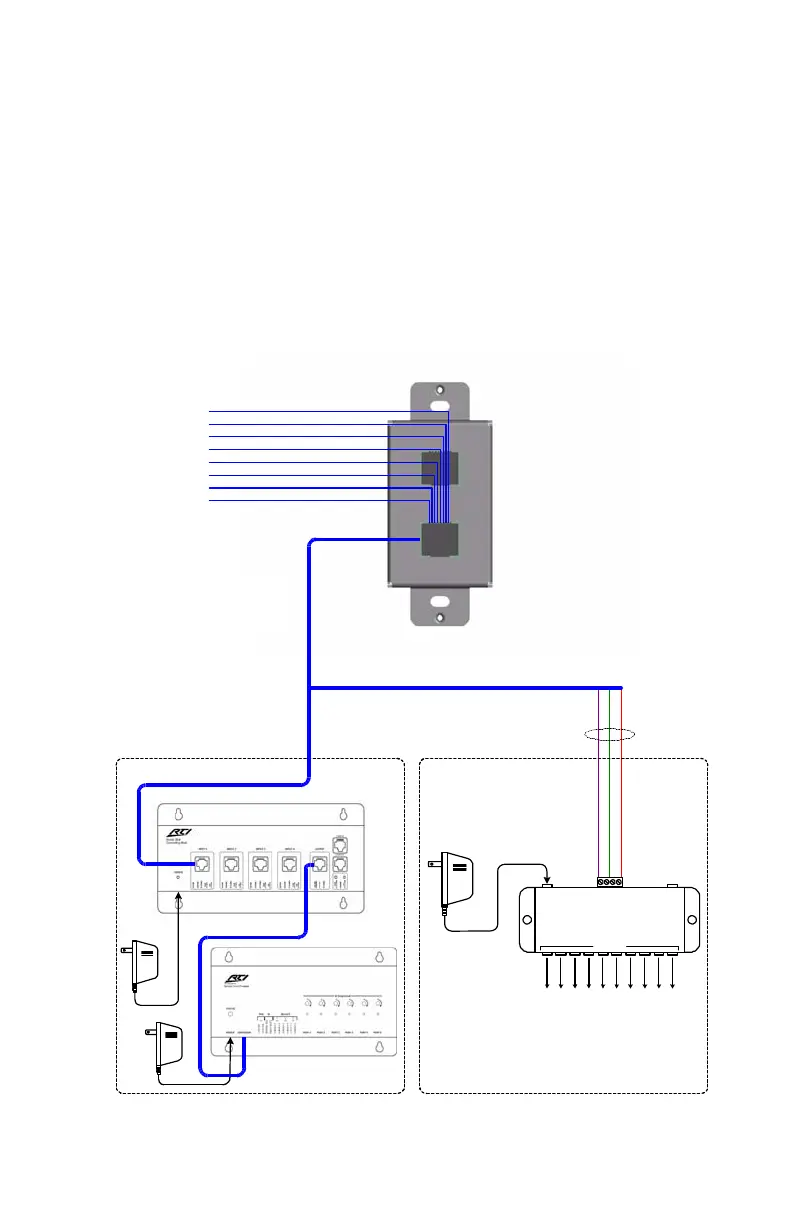
Control Port Pin-Out
Pin 1
Pin 2
Pin 3
Pin 4
Pin 5
Pin 6
Pin 7
Pin 8
INFRARED
INFRARED
+16VDC
+16VDC
IR Emitter Connecting Block
(Industry Standard)
EMITTERS
INPUT
To IR receivers on A/V
equipment, lighting controls, etc.
RK1 Basic Wiring Connections
RK1 Power Supply
16VDC
PWR
Stand-Alone OperationControl-System Operation
Cat-5 Cable
Use full Cat-5 pairs
(Future Use)
(Future Use)
Optional CB-4 Connecting Block(s)
RP-6 Remote Control Processor
Cat-5 Cable
CB-4 Power
Supply
16VDC
RP-6
Power
Supply
GROUND
GROUND
RS-485 +
RS-485 -
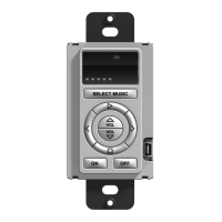
Chapter 4. Installation & Programming
The RK1 is designed for flush-mount installations in walls or
cabinets. It requires an available mounting depth of 2.0 inches
(50mm) from the front surface of the wall. Normally, the RK1 is
mounted in a standard single-gang electrical box or mud-ring.