13
It’s Under Control
®
CHAPTER 3 | INSTALLATION AND OPERATION
MOUNTING
The XP-6 can be wall mounted (details below) or free standing.
The XP-6 does not need to be mounted near the equipment being
controlled. The IR output ports and the optional Power Sensor modules can
be extended up to 1000 feet. If RS-232 control ports or Communication
Module (CM-232) are used, the distance limitation is 50-100 feet.
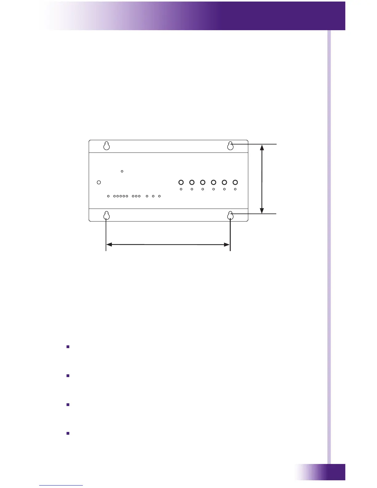
MOUNTING PATTERN
4.4 x Inches (112 mm)
8.0 Inches (203 mm)
POWER
The included AC adapter should be connected to the POWER jack on the
XP-6. The power LED will turn-on and the output LEDs will toggle on and
off in sequence to conrm that the unit is running properly.
Use only the supplied AC adapter to power the XP-6. Using a different
power supply could result in damage to the XP-6 or poor performance.
POWER/IR TERMINALS AND CONNECTIONS
TERMINAL: +12VDC
Positive power supply connection. It is internally tied to the Power
jack. This can be used to power external IR or RF receivers.
TERMINAL: GROUND
Common ground connection. Use this ground reference for any device
that is connected to the +12VDC, SIGNAL IN, OR HIGH OUT terminals.
TERMINAL: SIGNAL IN
Input connection for system trigger codes. This should be connected to
an RTI RF receiver or industry standard IR repeater system.
TERMINAL: HIGH OUT
High current (200mA) IR output connection. This can be used to power
up to 10 infrared mini-emitters, an IR blaster, or extending IR control
over a long distance (1000 ft. max).