Einbau- und Betriebsanleitung
Installation and Operating instructions
Instructions de montage et de service
5112-8510
07/2009
2. Nachrüstung / Austausch Potentiometer:
1. Upgrade / replacement of the
potentiometer:
1.
mélioration / Remplacement du
potentiomètre:
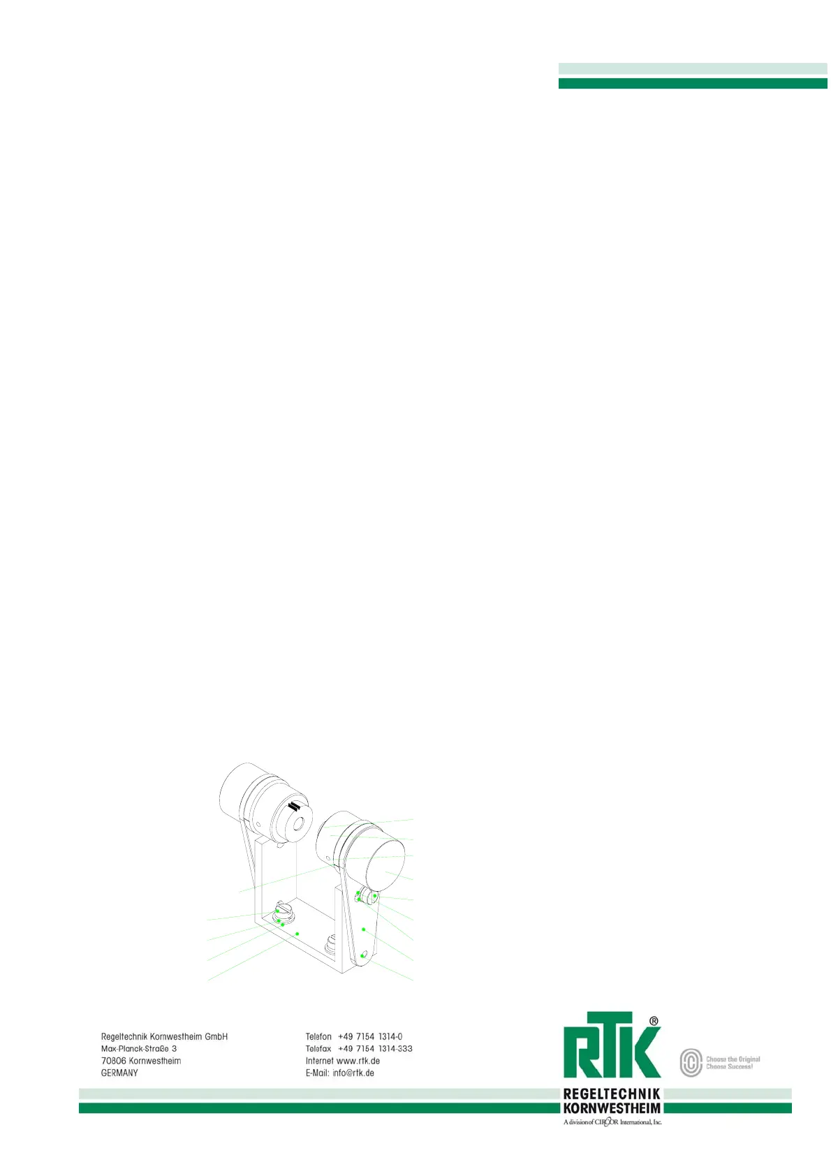
1. Montagewinkel (1) mit je 2 Linsenschrauben
M4x10 (3), Federringen (4) und Scheiben (5)
auf der Montageplatte fixieren.
2. Antrieb in die untere Endstellung bringen.
3. Gewindestift M 2,5 (10) an der Markierung
des Stellrings (8) lösen (nicht jedoch die auf
der gegenüberliegenden Seite der Markie-
rung), so daß sich das Ritzel (9) auf der Poti-
welle drehen läßt.
4. Hebel (6) auf Steckkerbstift (2) aufsetzen und
mit Linsenschraube M4x10 (11), Federring
(12) und Scheibe (13) so festklemmen, daß
das Ritzel im Eingriff mit der Zahnstange
steht.
5. Markierungen des Stellrings und des Hebels
in Übereinstimmung bringen und danach das
Ritzel durch anziehen des Gewindestifts fixie-
ren.
6. Spiel des Ritzels zur Zahnstange kontrollieren
und ggf. nachstellen. Das Ritzel soll zur
Zahnstange ein kaum merkliches Spiel auf-
weisen, aber nicht auf der Zahnstange pres-
sen.
7. Leiterplatte (16) mit 2 Gewindeschneid-
schrauben in der dafür vorgesehenen Position
auf dem Montagewinkel befestigen.
8. Kundenseitige Verdrahtung an der freien
Klemme der Leiterplatte vornehmen.
9. Für den Anbau von Potentiometer 2 sind die
Schritte 2 bis 8 analog auszuführen.
1. Fix mounting angle (1) with 2 oval-head
screws M4x10 (3), spring washers (4) and
washers (5) on the mounting plate.
2. Position drive in the lower final position.
3. Unscrew core pin M 2.5 (10) at the marking of
adjustable ring (8) (but not on the opposite
side of the marking) so that the pinion (9) can
be rotated on the potentiometer shaft.
4. Place lever (6) onto the dowel pin (2) and
clamp firmly using the oval-head screw
M4x10 (11), spring washer (12) and washer
(13) so that the pinion meshes with the
toothed rack.
5. Position both the adjustable ring and the lever
to align their markings, and then fix the pinion
by tightening the core pin.
6. Check gear clearance between pinion and
toothed rack, and adjust if necessary. The
clearance of the pinion should be almost im-
perceptible, but the pinion should not press
against the toothed rack.
7. Attach circuit board (16) using 2 thread cutting
screws in its position on the mounting angle.
8. Carry out on-site wiring using the unassigned
terminal of the circuit board.
9. Follow steps 2 to 8 when mounting potenti-
ometer 2.
1. Fixer l'angle de montage (1) sur la plaque de
montage avec 2 vis à tête bombée M4x10
(3), rondelles élastiques bombées (4) et ron-
delles (5).
2. Amener l'entraînement dans la position finale
inférieure.
3. Défaire la vis sans tête M 2,5 (10) au repère
de l'anneau ajustable (8) (mais pas au côté
opposé du repère), de façon à ce que le pi-
gnon (9) puisse être tourné sur l'arbre du po-
tentiomètre.
4. Mettre le levier (6) sur la goupille cannelée
d'ajustage (2) et serrer fortement avec la vis à
tête bombée M4x10 (11), rondelle élastique
bombée (12) et rondelle (13) , de façon à ce
que le pignon soit en contact avec la crémail-
lère.
5. Faire correspondre les repères de l'anneau
ajustable et du levier et puis fixer le pignon en
serrant la vis sans tête.
6.
Contrôler le jeu entre le pignon et la crémail-
lère et ajuster, si nécessaire. Le jeu entre le
pignon et la crémaillère devrait être quasi im-
perceptible, mais ne devrait pas pousser
contre la crémaillère.
7. Fixer la carte des circuits imprimés (16) avec
2 vis à taraudeuse dans la position prévue
pour cela sur l'angle de montage.
8. Effectuer le câblage incombant au client à la
borne de connexion libre de la carte des cir-
cuits imprimés.
9. Pour le montage du potentiomètre 2, il faut
suivre les étapes 2 à 8.
Achtung!:
Potentiometer 1 nur für rechtsseitigen Anbau
verwendbar!
Potentiometer 2 nur für linksseitigen Anbau
verwendbar!
Note:
Use potentiometer 1 for mounting on the right-
hand side only!
Use potentiometer 2 for mounting on the left-
hand side only!
Attention!:
utilisez le potentiomètre 1 pour un montage
au côté droit!
utilisez le potentiomètre 2 pour un montage
au côté gauche!
6
2
12
13
11
7
10
8
9
Markierung/ Marking / repère
3
4
5
1
Technische Änderung vorbehalten/ Subject to technical alteration/ Sous réserve de modifications techniques
 Loading...