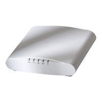
R510 Access Point
Quick Setup Guide
This Quick Setup Guide provides step-by-step instrucons on how to set up
your Ruckus Wireless R510 Dual Band 802.11ac Mulmedia Wi-Fi Access
Point. Aer compleng the steps described in this Guide, you will be able
to place the Access Point (AP) at your site and provide wireless network
access to users.
NOTE: The R510 requires a minimum of ZoneDirector version 9.13 or
later, or SmartZone rmware version 3.4 or later.
This Guide in Other Languages
• 请从以下网站获得该指南的简体中文版 hp://
docs.commscope.com/?docs-box.
• Vous trouverez la version française de ce guide à l'adresse suivante
hp://docs.commscope.com/?docs-box.
• このガイドの日本語版は hp://docs.commscope.com/?docs-box で
ご覧ください。
• 이 가이드의 한국어 버전은 웹 사이트 (hp://docs.commscope.com/?
docs-box) 에서 확인하시기 바랍니다.
• Veja a versão em português (Brasil) deste guia em hp://
docs.commscope.com/?docs-box
• Puede ver la versión en español (América Lana) de esta guía en hp://
docs.commscope.com/?docs-box
Before You Begin
Before deploying Ruckus products, please check for the latest soware and
the release documentaon.
• Release Notes and other user documentaon are available at hp://
support.ruckuswireless.com/documents.
• Soware upgrades are available at hp://support.ruckuswireless.com/
soware.
• Open source informaon is available at hp://
opensource.ruckuswireless.com.
• Soware license and limited warranty informaon are available at
hp://support.ruckuswireless.com/warranty.
NOTE: The minimum soware revision for the T305i is SmartZone (SZ)
5.1.1 New AP Model.
Package Contents
A complete R510 installaon package includes all of the items listed below:
• R510 Access Point
• One wall-mount anchor kit, including two 1" No. 8 steel panhead
Phillips sheet metal screws, one 5mm M2.5 x 1.06 Torx security screw,
and wall-mount anchors
• One external T-bar bracket (two unassembled parts)
• One unit removal pin
• Regulatory yer
• Product warranty statement
• Declaraon of Conformity, if required
• This Quick Setup Guide
Step 1: Collecng Setup Requirements, Hardware
and Tools
• A computer running Windows 7 (procedures for other OS’s are similar)
• Two Cat 5e Ethernet cables
• No. 2 Phillips screwdriver and T8 Torx driver for wall mounng anchor
kit
• An AC power adapter (sold separately), or
• an 802.3af or 802.3at -compliant Power over Ethernet (PoE) switch or
PoE injector
• When mounng the R510 to a truss or pole, two customer-supplied
cable es
IMPORTANT-QSG: If the AP is deployed with a ZoneDirector, then refer
to the ZoneDirector Quick Setup Guide and connect the AP to your local
network.
Step 2: Connecng Your Computer to the AP
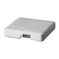
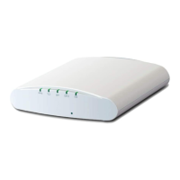
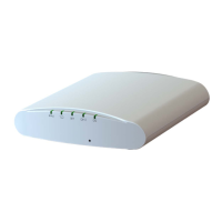
FIGURE 1 Top view
1. Aer removing your Ruckus AP from its package, place it next to your
computer.
2. Using an Ethernet cable, connect your computer’s network port to
one of the two ports on the AP.
3. Using an AC adapter (sold separately), connect the AP 12VDC port to
a protected power source.
Alternavely, connect the PoE port to a PoE injector or switch for
both power and network connecons
4. Verify that the Power LED on the external enclosure is slowly ashing
green.
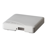
FIGURE 2
Boom view
1. Reset buon
2. PoE Port
3. 12V DC Port
CAUTION! The reset buon is accessible using a thin wire, for
example: a paperclip.
• To so reset, single press the reset buon.
• To factory reset the AP, press and hold the reset buon for more
than 3 seconds.
DO NOT RESET THE AP TO FACTORY DEFAULT SETTINGS UNLESS
SO INSTRUCTED. (Doing this resets the AP IP address to
192.168.0.1.)
Step 3: Preparing Your Computer for AP Setup
NOTE: The following procedures assume Windows as the operang
system. Procedures for other operang systems are similar.
1. On your Windows PC, congure your network adapter from the Local
Area Connecon sengs as follows:
Start > > Control Panel > Network and Sharing Center > Change
Adapter Sengs
2. Edit the TCP/IPv4 address sengs as follows:
Local Area Connecon > Properes > Internet Protocol Version 4
(TCP/IPv4) > Properes
The Internet Protocol Version 4 (TCP/IPv4) Properes dialog box
appears.
IMPORTANT-QSG: Write down all of the currently acve sengs
so you can restore your computer to its current conguraon later
(when this process is complete).
3. Select Use the following IP address (if it is not already selected) and
then make the following entries:
• IP address: 192.168.0.22 (or any available address in the
192.168.0.x network, except 192.168.0.1)
• Subnet mask: 255.255.255.0
• Default gateway: 192.168.0.1
Leave the DNS server elds empty.
Copyright
©
2024 CommScope, Inc. All rights reserved. Page 1 of 5
Published March 2024, Part Number 800-70940-001 Rev I