35.0
service
00497R0990 - 15-07-2000
T.D.C.T.D.C.
T.D.C.T.D.C.
T.D.C.
aa
aa
a
hh
hh
h
FIG. 1FIG. 1
FIG. 1FIG. 1
FIG. 1
FIG. 2FIG. 2
FIG. 2FIG. 2
FIG. 2
I.P.I.P.
I.P.I.P.
I.P.
P.M.S.P.M.S.
P.M.S.P.M.S.
P.M.S.
T.D.C. T.D.C.
T.D.C. T.D.C.
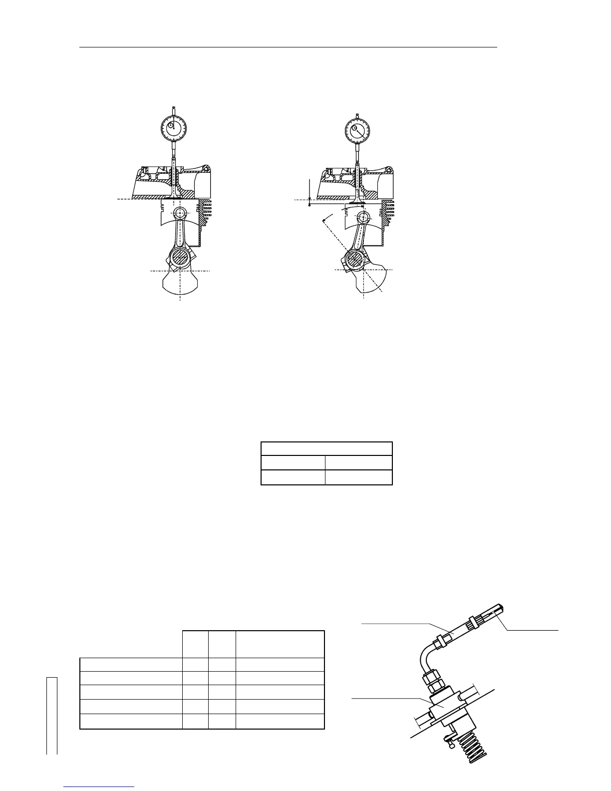
T.D.C. = top dead center
hh
hh
h = extent of piston lowering in
relation to T.D.C.
aa
aa
a = angle corresponding to piston
lowering in relation to T.D.C.
I.P. I.P.
I.P. I.P.
I.P. = start of delivery
Proceed in the following way:
1) Remove the cover from the rocker arms.
2) Demount the recoil and turn the drive shaft to the valve regulation position.
(This operation is carried out by means of the fylwheel nut, using a N° 32 socket wrench).
3) Demount the intake or exhaust rocker arm, the valve spring and caps.
4) Rest the valve top on the crown of the T.D.C. balanced piston (fig.1).
WARNING: The valve slips from its guide if the piston is lowered by turning the drive shaft more than 1/4 of a pipe wrenchWARNING: The valve slips from its guide if the piston is lowered by turning the drive shaft more than 1/4 of a pipe wrench
WARNING: The valve slips from its guide if the piston is lowered by turning the drive shaft more than 1/4 of a pipe wrenchWARNING: The valve slips from its guide if the piston is lowered by turning the drive shaft more than 1/4 of a pipe wrench
WARNING: The valve slips from its guide if the piston is lowered by turning the drive shaft more than 1/4 of a pipe wrench
turn.turn.
turn.turn.
turn.
5) Position a comparator mounted on a magnetic pedestal or dummy injector and reset it on the valve stem (fig.1).
6) Slowly turn the drive shaft in an anti-clockwise direction and check the comparator to make sure that the piston drops about 5 mm
in relation to T.D.C. (dimension "h" - fig. 2).
7) Slowly turn the drive shaft in a clockwise direction and check the comparator to make sure that the piston rises by the values
indicated in the following table, in relation to T.D.C. (dimension "h" - fig. 2):
8) Remove the injection tube and mount the capillary tube
code 365.94code 365.94
code 365.94code 365.94
code 365.94 on the injection pump delivery fitting (fig. 3).
9) Turn the accelerator lever to the MAX position and the stop lever to about half travel.
10) Turn the drive shaft anti-clockwise by no more than 1/4 of the pipe wrench turn.
11) Pressurize the circuit by turning the drive shaft several times in an alternate clockwise/anti-clockwise way until fuel splashes out
of the calibrated hole of the capillary tube.
12) Turn the drive shaft and check the comparator to make sure that the piston drops about 10 mm in relation to T.D.C. (dimension
(quota "h" - fig. 2).
13) Shake the capillary tube until an air bubble forms inside it (fig. 3).
14) Turn the drive shaft in a clockwise direction very slowly and check the position of the air bubble in the capillary tube. A small
movement of this bubble will indicate the exact lead position. This value must correspond to the one previously read on the
comparator (see point 7). If this is not the case, add or remove seals to or from the injection pump according to the corrections
indicated in the following table:
LEAD
hh
hh
h
4.12 mm
aa
aa
a
24°
SUGGESTIONS ON HOW TO TIME THE INJECTION PUMP WHEN THE LEAD PUNCH MARKS ON
THE FLYWHEEL ARE DIFFICULT TO REACH.
(Consult chapter 12.17 on page 29 for a description of the conventional adjustment)
Seal thickness for lead Seal thickness for lead
Seal thickness for lead Seal thickness for lead
Seal thickness for lead
correctioncorrection
correctioncorrection
correction
hh
hh
h
3.50
3.80
4.124.12
4.124.12
4.12
4.50
4.85
aa
aa
a
22°
23°
24°24°
24°24°
24°
25°
26°
- 0.2 mm
- 0.1 mm
00
00
0
+ 0.1 mm
+ 0.2 mm
Value off tolerance
Value in MIN. tolerance
STD. LEADSTD. LEAD
STD. LEADSTD. LEAD
STD. LEAD
Value in MAX. tolerance
Value off tolerance
Comparative lead adjustment tableComparative lead adjustment table
Comparative lead adjustment tableComparative lead adjustment table
Comparative lead adjustment table
FIG. 3FIG. 3
FIG. 3FIG. 3
FIG. 3
Injection pumpInjection pump
Injection pumpInjection pump
Injection pump
Capillary tubeCapillary tube
Capillary tubeCapillary tube
Capillary tube
365.94365.94
365.94365.94
365.94
Bolla d'ariaBolla d'aria
Bolla d'ariaBolla d'aria
Bolla d'aria