MODEL:F67Q/F71Q/F68Q/F69Q/F116Q/F117Q
15
●If the water outlet or water tank is installed higher than control valve or
parallel interlock system with multi-outlets, a liquid level controller must
be installed in brine tank, or install a check valve in water outlet. Or else,
the water in water outlet or water tank will flow backwards into
brine tank when backwash. The water in water outlet or water tank
will flow backwards into drain when brine refill
— Suitable for
F68Q/F69Q/F116Q/F117Q.
●If use a soldered copper to install inlet/outlet pipes, do all sweat
soldering before connecting pipes to the valve. Torch heat will damage
plastic parts.
●When turning threaded pipe fittings onto plastic fitting, do not use
excessive force to make threads misaligned or break valve.
●If the valve belongs to time clock type, there is no step ② and ③
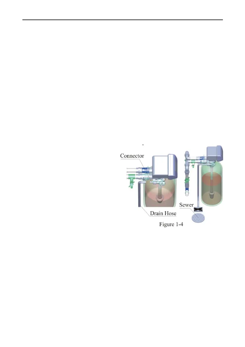
⑤ Install drain pipeline
a. As the Figure 1-4 shows,
slide the drain hose connector
into drain outlet.
b. Locate the drain hose well as
the Figure 1-4 show.
Note:
●Control valve should be higher
than drain outlet, and not far from the drain hose. If drain outlet higher
than control valve, a check valve must be installed in drain outlet. Or
else, the waste water will flow backwards into water outlet when
brine refill
—Suitable for F68Q / F69Q / F116Q / F117Q.
● Be sure not to connect drain with sewer, and leave a certain space
between them, avoid waste water being absorbed to the water treatment
equipment, such as showed in the Figure1-4.
⑥ Connect brine tube
a. As Figure 1-5 shows, slide 3/8″ brine tube hose connector over end of