4
7. Back Panel Connections
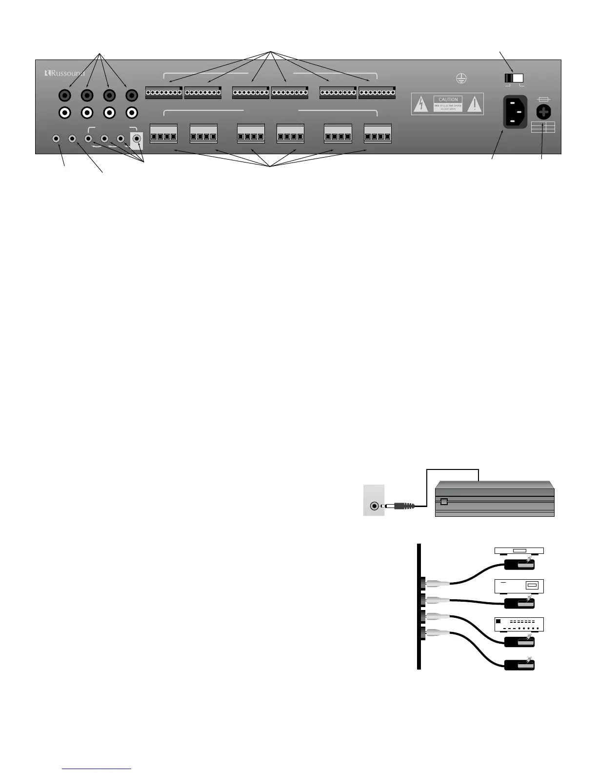
7.1 Source Input Connections
• Your source inputs are located at the top left corner of the back panel. Although the source input names are silk screened on the back
of the CA6.4, these names are for reference. Any type of source equipment can be connected to any input. Connect each source out-
put, left and right, using quality signal cables / patch cables. Label each cable the name of your source and the input number of the
CA6.4 you have selected. Repeat until all sources are connected. List them down below.
List 1 – Source names should be written below
Input 1 (TUNER) ______________ Input 2 (CD) ______________ Input 3 (TAPE) ______________ Input 4 (AUX) ______________
7.2 Speaker Connections
• Each speaker connection on the back panel corresponds to one room/zone. Wire your speakers by first removing the connector for
the chosen zone. Using wire strippers, strip back 1/8" of the end of the wire. Insert the proper polarity, left + to left +, left- to left- etc.,
until all wires are connected in each zone output. Label each wire with the room name and zone number. Write down the room
name to the zone number below. Note: We recommend 8 Ohm minimum speakers for each zone. However, speakers as low as 4
Ohm can be safely used in up to two zones, if necessary.
List 2 – Wire color should be written below
(Color) Left + _______________ Left - _______________ Right + _______________ Right - _______________
List 3 – Room names should be written below
Zone 1 ____________________________ Zone 2 ____________________________ Zone 3 ____________________________
Zone 4 ____________________________ Zone 5 ____________________________ Zone 6 ____________________________
7.3 12-Volt Trigger Output
The 12 volt trigger is engaged when any of the zones are on. The trigger can be
used to engage any 12 volt triggered accessory, such as a triggered AC outlet or
audio amplifier. The connection for the trigger is made by an 1/8” phono jack. The
tip is (+) and sleeve is (-).
7.4 Connecting The Infrared Components
• In order for your CA6.4 to transmit the IR signal from the keypads to a source, an emitter must
be connected from the IR outputs marked 1-4. Each of these outputs is wired in series and
must be connected in consecutive order. For example, the #1 emitter output must
be connected in order for the #2 emitter output to transmit the IR command.
• Connect each 845.1 mini-emitter to the source IR output. Refer to the source
number you had written down in list 1.
• Remove the adhesive back and position the IR receiver on the product you wish to control.
Stick the 845.1 emitter directly over the source components IR window. The CA6.4 will
direct the IR command to the source component you wish to control.
• Repeat connections until all emitters match the selected sources.