TRAMPOLINE FRAME ASSEMBLY
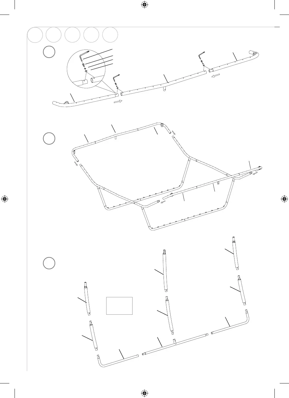
Step 5 –Side Leg Support Assembly
A. Lay out all parts shown below in FIGURE 7.
B. Connect Left L-Shape Base (# 10) and Right L-Shape Base (# 11) to the two ends of T-Shape Base (# 12)
using Arc Washer (# G), Spring Lock Washer (# E), Screw (# F) and Allen Wrench (# I) as shown in FIGURE 8.
4B
5A
TRAMPOLINE FRAME ASSEMBLY
Step 4 – Side Frame Assembly
A. Connect Corner Frame-Left (# 5) and Corner Frame-Right (# 6) to Short Frame with Leg Socket (# 4) using
Arc Washer (# G), Spring Lock Washer (# E), Screw (# F) and Allen Wrench (# I) as shown in FIGURE 5.
Please make sure all holes for springs are facing upward. Repeat in the same manner for the other set.
B. Attach the assembled Side Frames on both sides to form the trampoline frame as shown in FIGURE 6.
# E
# F
TRAMPOLINE FRAME ASSEMBLY
Step 4 – Side Frame Assembly
A. Connect Corner Frame-Left (# 5) and Corner Frame-Right (# 6) to Short Frame with Leg Socket (# 4) using
Arc Washer (# G), Spring Lock Washer (# E), Screw (# F) and Allen Wrench (# I) as shown in FIGURE 5.
Please make sure all holes for springs are facing upward. Repeat in the same manner for the other set.
B. Attach the assembled Side Frames on both sides to form the trampoline frame as shown in FIGURE 6.
4A
x2
ENG
SE NO DE FI
60
IM_759013120301_Trampoline_Advanced_550x400cm_v3.indd 60 2021-01-27 17:49