DISASSEMBLY OF THE TRAMPOLINE AND ENCLOSURE
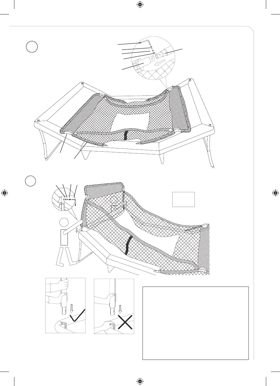
Step 17
Slide Curved Vertical Tube (# 23) into the bottom sleeves of Enclosure Netting (# 29) as shown in FIGURE 27.
Repeat the same for all Curved Vertical Tubes.
Step 18
Connect Curved Vertical Tube (# 23) to Arched Tube (# 28) using Arc Washer (# G), Spring Lock Washer (# E),
Screw (# F) and Allen Wrench (# I) as shown in FIGURE 28. Repeat the same for all four tubes.
18
DISASSEMBLY OF THE TRAMPOLINE AND ENCLOSURE
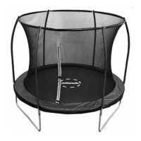
Step 19
With one person at each end holding the tubes steady, lift up the Curved Vertical Tube (# 23) assembled in the
previous step and insert it) into the sockets on Corner Frame-Right (# 5) and Corner Frame-Left (# 6). Secure
using Arc Washer (# G), Spring Lock Washer (# E), Screw (# F) and Allen Wrench (# I) as shown in FIGURE
29. Repeat the same for the other side.
DO NOT PLACE HANDS NEAR THE OPENING WHEN CONNECTING THE TUBES. WEAR
PROTECTIVE GLOVES TO PROTECT FROM INJURIES DURING ASSEMBLY.
DISASSEMBLY OF THE TRAMPOLINE AND ENCLOSURE
Step 19
With one person at each end holding the tubes steady, lift up the Curved Vertical Tube (# 23) assembled in the
previous step and insert it) into the sockets on Corner Frame-Right (# 5) and Corner Frame-Left (# 6). Secure
using Arc Washer (# G), Spring Lock Washer (# E), Screw (# F) and Allen Wrench (# I) as shown in FIGURE
29. Repeat the same for the other side.
DO NOT PLACE HANDS NEAR THE OPENING WHEN CONNECTING THE TUBES. WEAR
PROTECTIVE GLOVES TO PROTECT FROM INJURIES DURING ASSEMBLY.
x2
WARNING! Never place your hands near the tube
openings! Risk of trapping! Always use gloves. /
VARNING! Placera aldrig händerna i närheten
av rörens öppningar, klämrisk! Använd alltid
handskar. / ADVARSEL! Plasser aldri hendene
nær røråpningene på grunn av klemrisiko!
Bruk alltid hansker. /WARNUNG! Niemals
die Hände in der Nähe der Rohröff nungen
halten. Quetschgefahr! Verwenden Sie immer
Handschuhe. / VAROITUS! Älä koskaan
aseta käsiäsi putkien aukkojen lähelle
puristumisvaaran takia! Käytä aina käsineitä.
17
DISASSEMBLY OF THE TRAMPOLINE AND ENCLOSURE
Step 17
Slide Curved Vertical Tube (# 23) into the bottom sleeves of Enclosure Netting (# 29) as shown in FIGURE 27.
Repeat the same for all Curved Vertical Tubes.
Step 18
Connect Curved Vertical Tube (# 23) to Arched Tube (# 28) using Arc Washer (# G), Spring Lock Washer (# E),
Screw (# F) and Allen Wrench (# I) as shown in FIGURE 28. Repeat the same for all four tubes.
# F
# E
# G
79
IM_759013120301_Trampoline_Advanced_550x400cm_v3.indd 79 2021-01-27 17:49