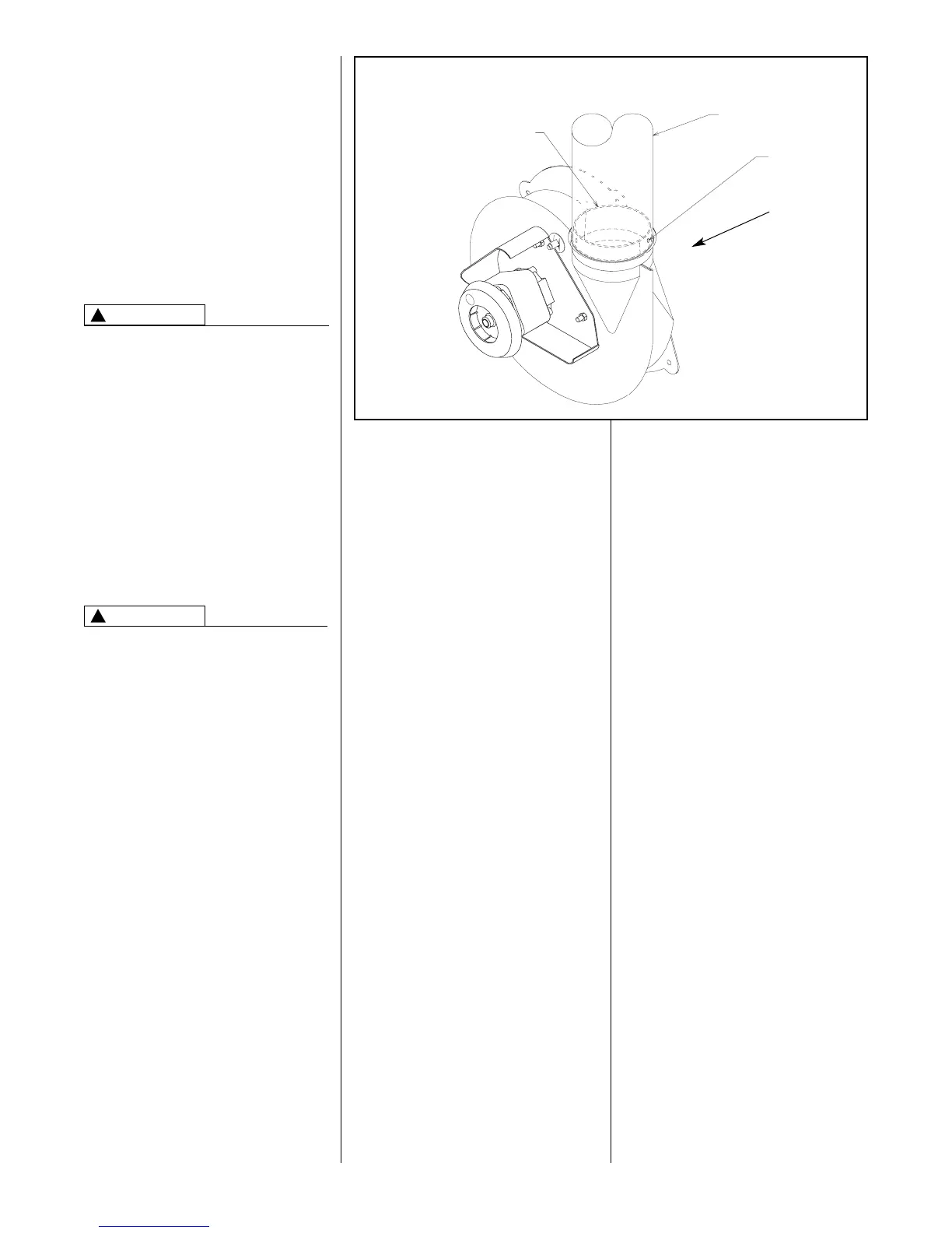
FIGURE 9
ATTACHING TO DRAFT INDUCER COLLAR
13
GENERAL INFORMATION
The furnace must be vented in
accordance with these instructions,
National Fuel Gas Code, ANSI Z223.1
and/or the Natural Gas Installation
Code, CSA-B149.1 & .2 and
requirements or codes of the local utility
or other authority having jurisdiction.
IMPORTANT: This furnace is not
certified for use with a power venter or
any other type of horizontal venting.
DEVICES ATTACHED TO THE FLUE
OR VENT FOR THE PURPOSE OF
REDUCING HEAT LOSS UP THE
CHIMNEY HAVE NOT BEEN TESTED
AND HAVE NOT BEEN INCLUDED
IN THE DESIGN CERTIFICATION OF
THIS FURNACE. WE, THE
MANUFACTURER, CANNOT AND
WILL NOT BE RESPONSIBLE FOR
INJURY OR DAMAGE CAUSED BY
THE USE OF SUCH UNTESTED
AND/OR UNCERTIFIED DEVICES,
ACCESSORIES OR COMPONENTS.
DRAFT INDUCER
VENT PIPE ATTACHING HOLES
MUST BE PREDRILLED IN THE
DRAFT INDUCER COLLAR TO
PREVENT PLASTIC MATERIAL
FROM CRACKING. DRILL 1/8
DIAMETER HOLES THROUGH THE
VENT PIPE AND COLLAR AND USE
#8 SCREWS TO ATTACH. SEE
FIGURE 9. FAILURE TO FOLLOW
THIS WARNING CAN CAUSE
RECIRCULATION OF FLUE
PRODUCTS CAUSING CARBON
MONOXIDE POISONING
RESULTING IN PERSONAL INJURY
OR DEATH.
NOTE: On downflow units, be certain
that the vent pipe is positioned over
the induced draft motor outlet. Attach
the vent pipe to the induced draft
motor collar as noted above.
IMPORTANT APPLICATION
NOTES
When the furnace is used as a
replacement, the existing vent system
should be inspected to assure that
there are no obstructions, blockage, or
any signs of corrosion.
NOTE: When the vent table permits
more than one diameter of pipe for a
connector or vent, the smallest
permitted diameter must be used, vent
pipe may be type “B-1,” either rigid or
suitable flexible construction that
carries a U.L. listing.
Common venting is allowed with
vertical B-1 vent systems, and lined
masonry chimneys. Follow the National
Fuel Gas Code, ANSI Z223.1 and/or
the Natural Gas Installation Code,
CSA-B149.1 & .2 for proper installation
practices.
Single wall vent connectors to “B-1
vent or masonry chimneys” may be
used under the guidelines of the
National Fuel Gas Code, ANSI Z223.1
and/or the Natural Gas Installation
Code, CSA-B149.1 & .2.
The entire length of the vent
connector shall be readily
accessible for inspection, cleaning
and replacement.
WARNING
!
WARNING
!
FURNACE CATEGORY
INFORMATION
This furnace is shipped as a Category I
type induced draft furnace. A Category
I furnace operates with a nonpositive
vent pressure and has a vent gas
temperature at least 140°F above the
dew point of the vent gases. A
Category I type may be a draft hood
equipped furnace or have a fan
assisted combustion system (induced
draft). The inducer is used to pull flue
products through the combustion
chamber and as they leave the
furnace, most of the energy has been
dissipated. The buoyant effect of the
flue gases provides venting to the
outdoors.
During the off cycle, the inducer is off
and there is very little flow through the
vent, cooling the vent. During the on
cycle there is no dilution airflow, as
with a draft hood type furnace.
Although the vent heats up rapidly
without dilution air, the flue products
contain more water vapor, which
results in a higher dew point
temperature. It is most important that
you follow the guidelines in these
instructions to prevent the possible
formation of condensation in the
venting system.
As a Category I furnace it may be
vented vertically with type B-1 vent
pipe and also may be common vented,
as described in these instructions.
VENTING
A0991-01
VENT PIPE
ADAPTER
CONNECTOR*
*SEE PAGE 14
VERTICAL VENTING
PRE-DRILL
ATTACHING
HOLES
DRAFT INDUCER
OUTLET


 To Next Page