18
SETTING GAS PRESSURE
The maximum gas supply pressure to
the furnace should be 10.5” w.c.
natural gas, or 13” w.c. LP gas. The
minimum supply gas pressure to the
gas valve should be 5" w.c. natural gas
or 11" w.c. LP gas. A properly
calibrated manometer is required for
accurate gas pressure measurements.
ELEVATIONS ABOVE 2000 FT
REQUIRE THAT THE FURNACE
INPUT RATING BE ADJUSTED AND
THAT THE SIZE OF THE BURNER
ORIFICES BE RE-CALCULATED
BASED ON ELEVATION AND GAS
HEATING VALUE. THE BURNER
ORIFICES MAY (OR MAY NOT)
NEED TO BE CHANGED. SEE THE
SECTION TITLED “HIGH ALTITUDE
INSTALLATIONS” OF THIS BOOK
FOR INSTRUCTIONS.
Manifold Gas Pressure
Measurement. Natural gas manifold
pressure should be 3.5" w.c.; LP gas
manifold pressure should be 10"
w.c. Only small variations on gas
pressure should be made by adjusting
the pressure regulator.
1. With the gas shut off at the manual
gas valve, remove the pressure
tap plug in the gas manifold or the
gas valve outlet. See Figure 26.
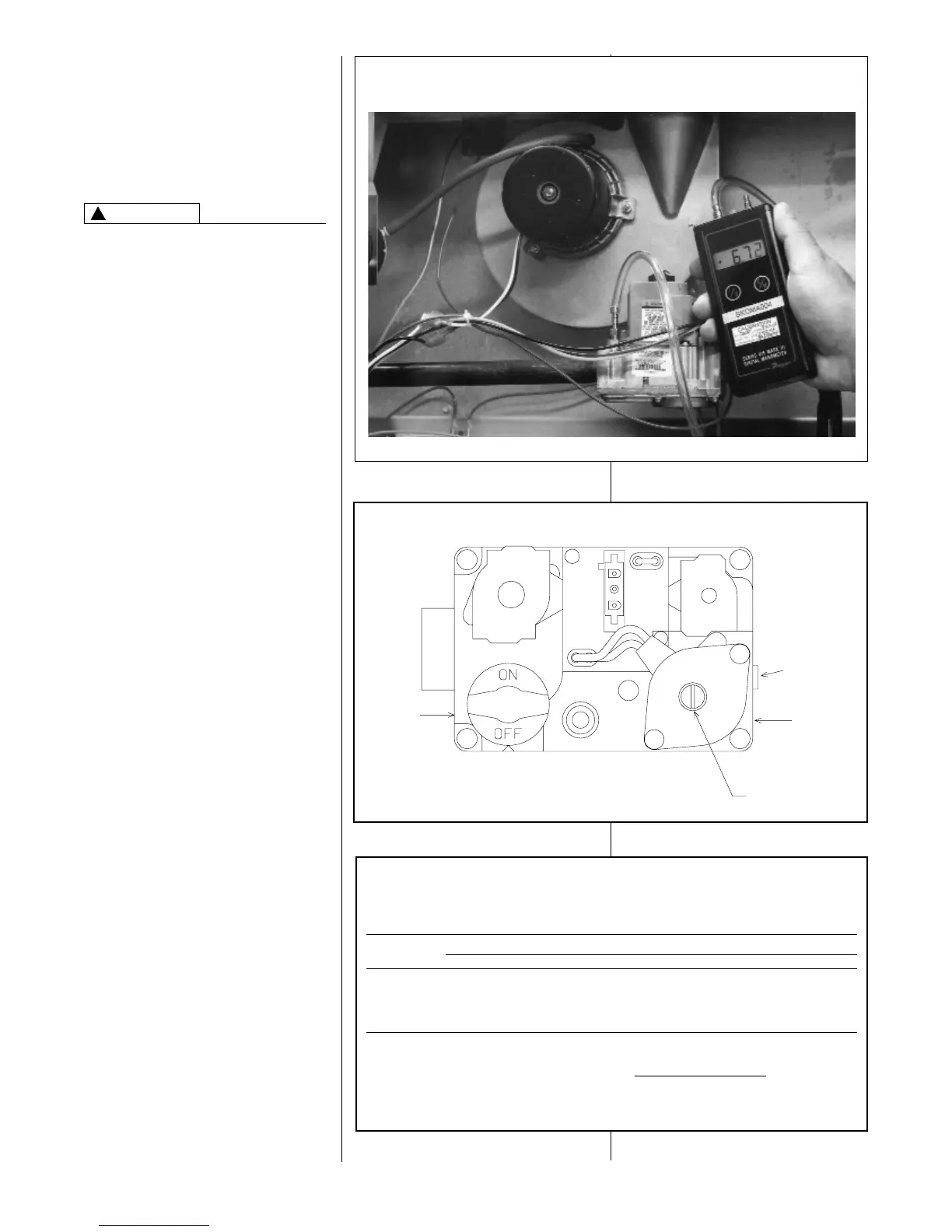
2. Connect a U-Tube manometer to
this pressure tap. See Figure 27.
3. Turn on the gas supply and
operate the furnace in high speed.
4. Note or adjust the manifold gas
pressure to give:
A. 3.5" w.c. for natural gas high fire.
B. 10" w.c. for LP gas high fire.
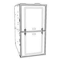
5. To adjust the pressure regulator
for high fire, remove the regulator
cap located on the
side of the
regulator.
See Figure 14.
6. Turn the adjustment screw
clockwise to increasre pressure or
counterclockwise to decrease
pressure.
7. Securely replace the regulator cap
for high fire.
8. Operate the furnace in low speed.
9. Note or adjust the manifold
pressure to give:
A. 1.7" w.c. for natural gas low fire.
B. 4.9" w.c. for LP gas low fire.
10. To adjust the pressure regulator
for low fire, remove the regulator
cap
on the top of the regulator.
See Figure 14.
11. Turn the adjustment screw
clockwise to increase pressure or
counterclockwise to decrease
pressure.
12. Securely replace the regulator cap
for low fire.
TABLE 2
NATURAL GAS PIPE CAPACITY TABLE (CU. FT./HR.)
Capacity of gas pipe of different diameters and lengths in cu. ft. per hr. with pressure drop of 0.3 in. and specific
gravity of 0.60 (natural gas).
Nominal Length of Pipe, Feet
Iron Pipe
Size, Inches 10 20 30 40 50 60 70 80
1/2 132 92 73 63 56 50 46 43
3/4 278 190 152 130 115 105 96 90
1 520 350 285 245 215 195 180 170
1-1/4 1,050 730 590 500 440 400 370 350
1-1/2 1,600 1,100 890 760 670 610 560 530
After the length of pipe has been determined, select the pipe size which will provide the minimum cubic feet per hour
required for the gas input rating of the furnace. By formula:
Gas Input of Furnace (BTU/HR)
Cu. Ft. Per Hr. Required =
Heating Value of Gas (BTU/FT3)
The gas input of the furnace is marked on the furnace rating plate. The heating value of the gas (BTU/FT3) may be
determined by consulting the local natural gas utility or the LP gas supplier.
FIGURE 14
TYPICAL GAS VALVE
INLET
PRESSURE
TAP
OUTLET
PRESSURE
TAP
HIGH FIRE
MANIFOLD
PRESSURE
ADJUSTMENT
LOW FIRE
PRESSURE
MANIFOLD
ADJUSTMENT
FIGURE 13
TYPICAL HOSE CONNECTION TO LINE PRESSURE TAP
!
CAUTION


 To Next Page