Replace the blade guard if no additional adjustments are
to be made.
Adjust Blade Guide Support:
Adjust the position of the blade guide assembly. Loosen
the
bottom screw on the right side of the blade guide
assembly
using the 4 mm h
ex key.
Slide the upper blade guide support on
the shaft until the
front edge of the blade guides are about
behind the gullet of the blade. Tighten the screw
securely.
Repeat this procedure for the lower blade guide
s
upport.
Replace the blade guard if no additional adjustments are
to be made.
NOTE:
The lower blade guide support screw (37) is the top screw
located on the right of the saw housing under the table (Fig. 11).
Never operate saw without blade guard secured in place.
To do so could result in possible serious personal injury.
To Adjust Blade Guides:
The blade guides help keep the blade from twisting and
binding. The blade will be ruined if the blade teeth hit the
blade guides while using the band saw. The set of teeth and
the sharpened edge of teeth will be damaged by hitting the
blade guides. Proper adjustment of the upper and lower blade
guides will prevent this from happening.
Turn the lock knob counterclockwise to unlock the blade
guide assembly.
Turning the blade guide knob clockwise,
Place a small combination square on the saw table
beside
the blade.
Loosen the ta
ble lock knob and rotate the angle
adjustment knob to tilt the saw table up or down to align
table 90
˚
to blade (0
˚
position). Retighten the table lock
knob.
Using a h
ex keys, adjust the zero stop set screw (33)
until the set screw just touches the saw housing.
Check squareness of the saw table to the blade. Make
readjustments if necessary.
Loosen screw on scale indicator with a phillips
screwdriver and align scale indicator to zero.
Tighten all screws securely.
Replace the blade guard once the saw table has been
squared.
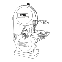
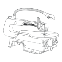
ADJUSTING THRUST BEARINGS, BLADE GUIDE
SUPPORT,
AND BLADE GUIDES (Fig. 10, 11, 12)
The upper and lower blade guides and thrust bearings
support the band saw blade during cutting operations. The
adjustment of the guides and bearings should be checked
whenever a different blade is installed.
To Adjust Thrust Bearings:
The thrust bearings support the back edge of the blade during
cutting. The blade should not contact the thrust bearings
(39) when you stop cutting. It is important that both upper
and lower thrust bearings be adjusted equally.
Adjust the thrust bearings first. Using the 4 mm hex key
,
l
oosen the thrust bearing screw
.
WARNING:
Close front cover and relatch.
NOTE: A
(1/8")
3 mm blade may
not
track properly in
the
center of the wheel. It may be b
etter to track this blade
on
the back half of the upper wheel.
WARNING:
SQUARING THE SAW TABLE TO THE BLADE (Fig. 9)
Failure to turn the saw off, remove the switch key and
unplug the saw could result in accidental starting causing
possible serious personal injury.
Remove the blade guard by loosening the two set
screws with 4mm hex key.
raise the blade guide assembly as far as it will go.
Retighten the blade guide knob.
Remove the blade guard by loosening the two set screws
with
4mm hex key.
Turn the lever counterclockwise to unloc
k the blade guide
assembly (24). Turning the blade guide knob (clockwise
raises
the blade guide assembly, counterclockwise lowers it),
position
the blade guide assembly about halfway between
the saw blade
and saw housing. Retighten the lock lever.
Move the thrust bearing
(39) to within (1/64")
0.4
of
the blade. Tighten the thrust bearing screw (38)
securely.
Repeat this procedure on the lower thrust
bearing located
below the saw table.
Remove the blade guard by loosening the two set screws
with 4mm hex key.
Remove the blade guard by loosening the two set screws
with 4mm hex key.
Rotate the upper wheel by hand in a clockwise direction
for a few more turns. Make sure the blade stays in the
same location on the tires. Readjust, if necessary, until
blade is tracking properly.
WARNING:
Failure to turn the saw off, remove the switch key and
unplug the saw could result in accidental starting causing
possible serious personal injury.
Loosen the two blade guide support screws that lock the
upper blade guides. Slide the two guides to within
of the blade. Do not pinch the blade. Make sure
one guide is not further away from the blade than the
other. Retighten the two blade guide support screws
securely.
R
eplace the blade guard if no additional adjustments
are
t
o be made.
Repeat this procedure on the lower blade guides located
under the saw table (Fig. 11).
located on the right side of the blade guide assembly. It
is the lower cap screw on the right side of the saw
housing
below the saw table for the lower bearing.
NOTE:
The thrust bearing screw is the upper cap screw
( 34)
mm
(1/64")
0.4
mm
(1/32")
0.8 mm