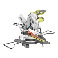
DEPTH OF CUT ADJUSTMENT(Fig. 24&25)
Unplug the power cord.
The saw blade can cut deeper by turning the depth
cut adjustment screw(26) counterclockwise and
cut lesser by turning this screw(26) clockwise.
Lower the blade into the throat plate of mitre table,
then check the maximum cutting depth.
Re-adjust if necessary.
To prevent the depth of cut adjustment screw
(26) from turning, tighten
the hex nut(a) carefully
against the fence(13).
WARNING: To avoid the risk of personal
injury or damage to the unit, check that the blade is
not in contact with an element of the table.
ADJUSTING THE MITRE LOCK (Fig. 26)
After
a period of time, you may need to readjust the
locking mechanism. To readjust:
Loosen the set screw under the mitre lock knob(9)
by a hex key. (Fig. 26a)
Turn the mitre lock knob(9) clockwise until the
turntable is firmly locked. (Fig. 26b)
Fasten the set screw so that the new turning angle
of the handle to lock the table is redefined. (Fig.
26c)
ADJUSTMENT
Unlock the bevel lock lever(16) and move the saw
arm to the 0
o
position and lock the bevel lock lever.
(Fig.16)
Lay the combination square(b) on the mitre
table(11) and against the blade(a). If the blade(a)
and mitre table(11) do not align, adjust as follows.
(Fig. 17)
Unscrew the 0
o
bevel positioning bolt on the right
hand side by using a hex key(a). (Fig.18)
Correctly align the blade(a) and mitre table (11)
using
the combination square and lock the bevel
lock lever. ( Fig.19)
Retighten the 0
o
bevel positioning bolt(a). Check
0
o
angle from the table to the blade again. If the
table and the blade do not align, readjust the 0
o
bevel positioning bolt until aligned(Fig. 20), then
adjust the pointer(b) to 0
o
mark and secure by
tightening the pointer screw(c) (Fig. 21).
SQUARING THE BLADE TO THE MITRE
TABLE AT
45
O
(Fig. 22&23)
Move the saw arm to the 45
o
bevel position. (Fig.
22)
When the saw arm is rotated at the 45
o
bevel
position, check 45
o
angle by using at 45
o
set
square from the table to the blade. If the table and
blade do not align, readjust the 45
o
positioning
bolt(a) on the left until aligned. (fig. 22-23)
Page 14
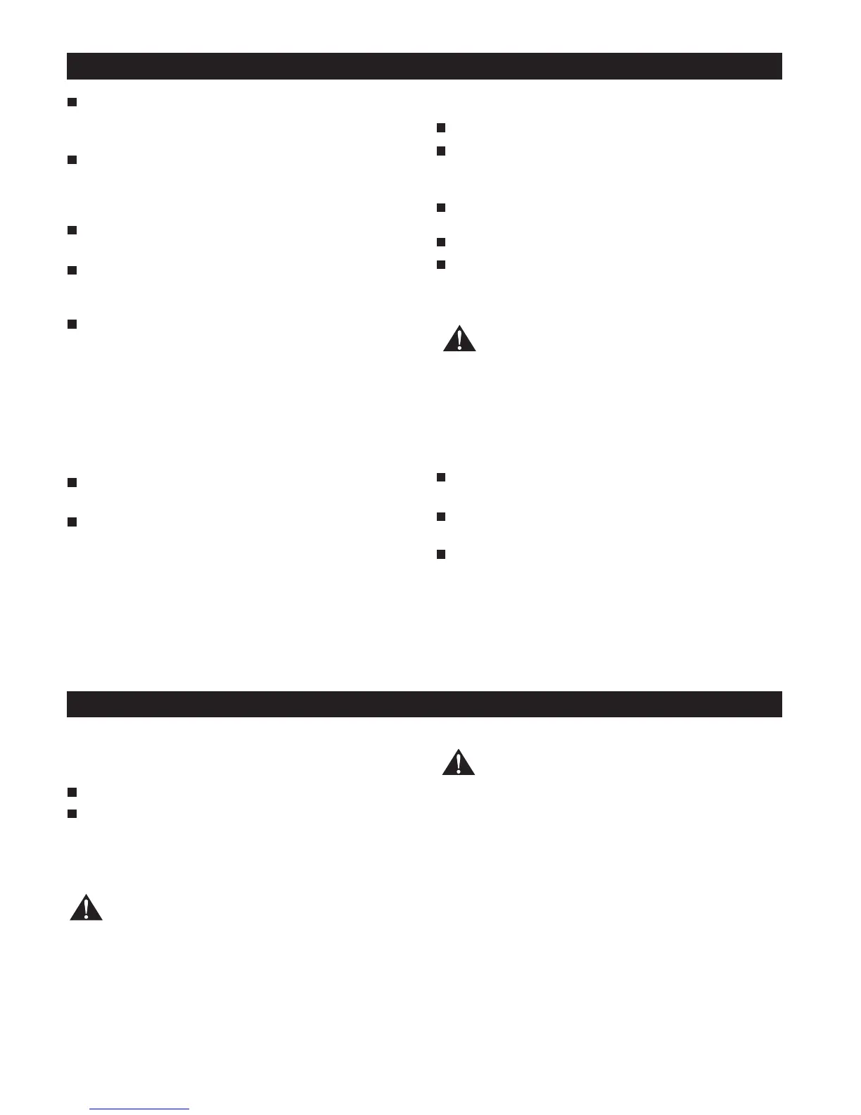
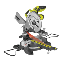
OPERATION
APPLICATIONS
(Use only for the purposes listed below)
Cross Cutting wood.
Cross Cutting mitres, joints etc., for picture frames,
moldings, door casings and fine joiner
y.
NOTE: The crosscut blade provided is for most wood
cutting oper
ations.
WARNING: Before starting any cutting
operations, clamp or bolt your compound mitre saw
to a workbench. Never operate your mitre saw on the
floor of in a crouched postion. Failure to heed this
warning can result in serious personal injury.
CUTTING WITH YOUR COMPOUND MITRE SAW
WARNING: Use the vice to secure your
workpiece on one side of the blade only. The
workpiece must remain free on one side of the blade
to prevent the blade from binding in workpiece. The
workpiece binding blade will cause motor stalling
and kickback. This situation could cause an accident
resulting in serious personal injury.
LIVE INDICATOR (Fig. 27)
When the machine is connected with the power
supply, the live indicator(24) always glow. If not,
please check the supply.
CROSSCUTTING
A crosscut is made by cutting across the grain of
the
workpiece. A 90
o
crosscut is made with the mitre
table set at the zero degree position. Mitre crosscuts
are made with the mitre table set at some other angle
other than zero.