Page 13
ADJUSTMENTS
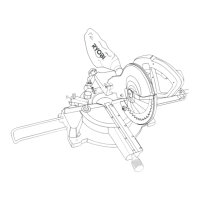
Your compound mitre saw has been adjusted
at the factory for making very accurate cuts.
However, some of the components might have
been jarred out of alignment during shipping. Also,
over a period of time, re-adjustment will probably
become necessary due to wear. After unpacking
your saw, check the following adjustments before
you begin using saw. Make any re-adjustments
that are necessary and periodically check the
parts alignment to make sure that your saw is
cutting accurately.
WARNING: To prevent accidental starting
that could cause possible serious personal injury,
assemble all parts to your saw before connecting
it to the power supply. The saw should never be
connected to power supply when you are assembling
parts, making adjustments, installing or removing
blades or when not in use.
As mentioned previously your saw has been
factory assembled and adjusted. The dust bag,
vice and material supports are the only parts that
have to be installed.
REPLA
CING BLADE (Fig. 10, 11&12)
DANGER: A 254mm x 2.0mm diameter
blade is the maximum blade capacity of your saw.
Never use a blade that is too thick to allow outer
blade washer to engage with the flats on the spindle.
Larger blades will come in contact with the blade
guards, while thicker blades will prevent the blade
screw from securing the blade on the spindle. Either
of these situations will result in a serious accident
and can cause serious personal injury.
Remove the screw(a) on the link(c) and loosen
the
philips screw on the blade bolt cover until the
lower blade guard(4) assembly can be raised to
expose the blade bolt. (Fig. 10)
Depress the spindle lock button(15) while rotating
the blade. (Fig. 11)
Loosen screw(a) and outer blade flange(b) to
replace the blade(c). Use wrench(d) to loosen the
blade bolt. Please Note - This is a left hand thread,
so loosen in a CLOCKWISE direction(Fig. 12).
Remove the outer blade washer and the blade.
Fit the new blade onto the spindle.
Reattach
the outer blade flange and secure the
blade bolt tightly while depressing the spindle lock
button. (Fig.12)
Replace the blade bolt cover and the lower blade
guard in position. Fasten the philips screw on the
blade bolt cover.
Connect the link to the lower blade guard.
Check if the blade guard operates correctly before
connecting the saw to the power supply.
WARNING: If the inner blade washer has
been removed, replace it before placing blade on
spindle. Failure to do so could cause an accident
since the blade will not tighten properly.
CAUTION: Always install the blade with the
blade teeth pointing in a downward direction.
SQUARING THE SAW BLADE TO THE FENCE
(Fig. 13~17)
Unplug your saw.
Pull the saw arm all the way down and engage the
lock down pin(14) to hold the saw arm in transport
position.
Loosen the mitre loc
k knob(9). (Fig. 14a)
Rotate the mitre table(11) until the mitre pointer(c)
is positioned at 0
o
.(Fig. 14a&b)
Securely tighten the mitre lock knob(9).
Lay a framing square(a) flat on the mitre table(11).
Place one leg of the square against the fence(13).
Slide the other leg of the square against the flat
part of saw blade(b). (Fig.14a)
Note: Make sure that the square contacts the flat
par
t of the saw blade, not the blade teeth.
The edge of the square and the saw blade should
be par
allel as shown in Fig. 14a.
If the front or back edge of the saw blade
angles(a) away from the square as shown in Fig.
15, adjustments are needed.
L
oosen the fence screw(c) (Fig. 13) and the screw(a)
(Fig. 2), then remove the sliding fence (24).
Loosen the socket head screws(b) that secure the
rear f
ence(13) to the mitre table(11). (Fig. 13)
Slightly adjust the rear fence(13) left or right until
the saw blade is parallel with the square.
Retighten
the screws(b) securely and recheck the
blade to fence alignment.
Place
back the sliding fence(24) and screws (a
&c). (Fig. 2&13)
After squaring adjustments have been made, it may
be necessary to loosen the screw(d) of the pointer(c)
and reset the pointer to zero. (Fig. 14b)
SQUARING THE BLADE TO THE MITRE TABLE
(Fig. 16~21)
Pull the saw arm all the way down and engage the
lock down pin to hold the saw arm in the transport
position(14). (Fig. 7)