49 - English
MAINTENANCE
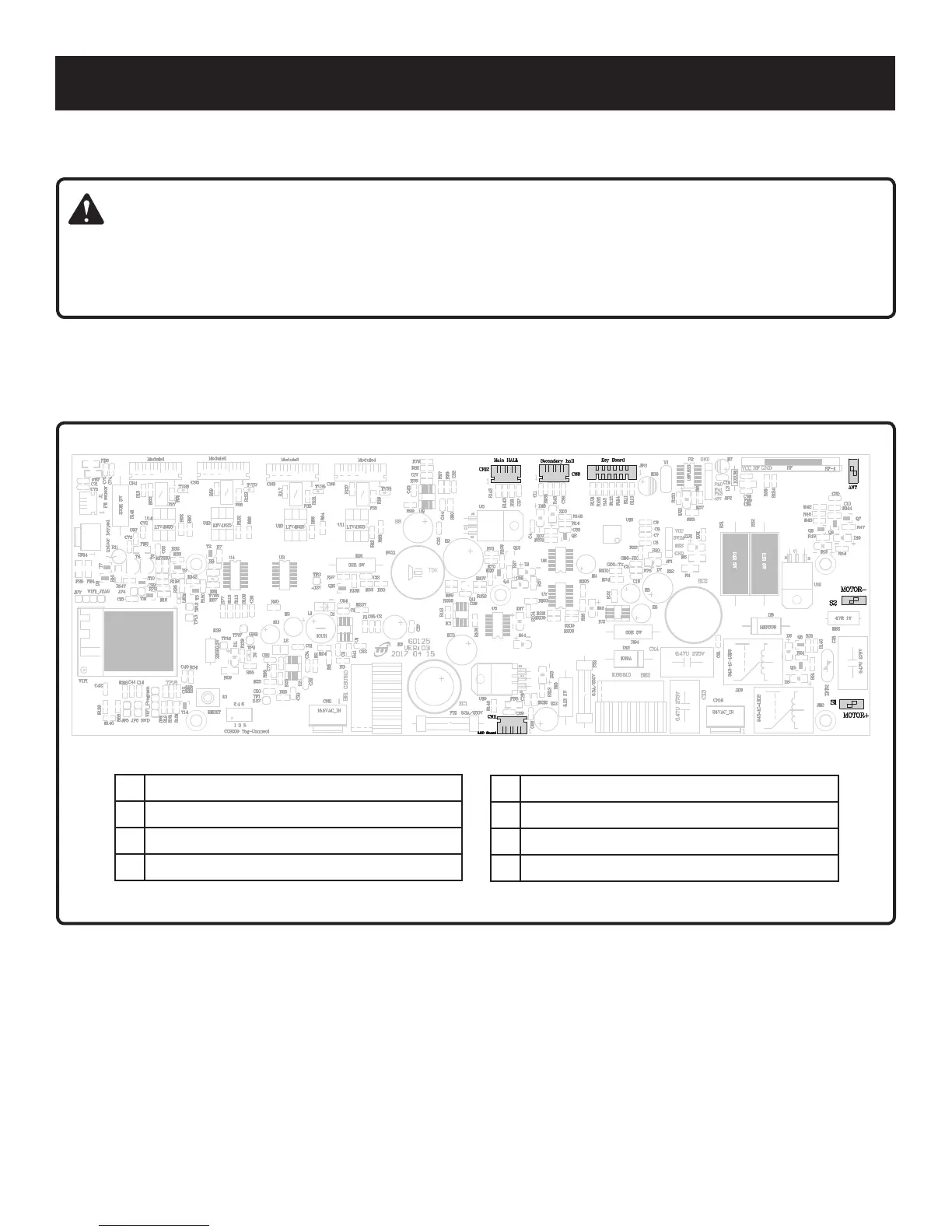
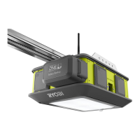
Fig. 88
A B
C
E
D
G
F
CIRCUIT BOARD
See Figure 88.
WARNING:
Ensure the garage door opener power head is disconnected from the power supply before disconnecting any wires from
the circuit board assembly. Have the maintenance performed by a qualified service person if you are not comfortable
performing any of these procedures. Improper handling of electrical and electronic components of the garage door
opener can result in death, serious personal injury, or property damage.
Some maintenance procedures will require you to disconnect wires from the circuit board assembly. Use the circuit board
schematic below to locate pin connections for the main hall, secondary hall, keyboard, ant, motor (-), motor (+), and LED
board wires.
NOTE: The schematic is oriented with the motor (+) pin connection in the bottom right corner.
A Main Hall
B Secondary Hall
C Key Board
D Ant
E Motor (-)
F Motor (+)
G LED Board