5
See Figure 6.
The drill has a two-speed gear train designed for drilling
or driving at or ) speeds. A slide switch is
located on top of the drill to select either or
speed. When using drill in the speed range, speed
will decrease and unit will have more power and torque.
When using drill in the speed range, speed will
increase and unit will have less power and torque. Use
speed for high power and torque applications and
speed for fast drilling or driving applications.
If you have difficulty changing from one gear
range to the other, turn the chuck by hand until the gears
engage.
Never change gears while the tool is running.
Failure to obey this caution could result in
serious damage to the drill.
See Figure 7.
The Quick Mode Selector allows you to quickly switch
from drill mode to drive mode.
In general, drill mode should be used for drilling and
other heavy duty applications. Drive mode should be
used for driving screws.percussion mode should be used
for impact drilling.
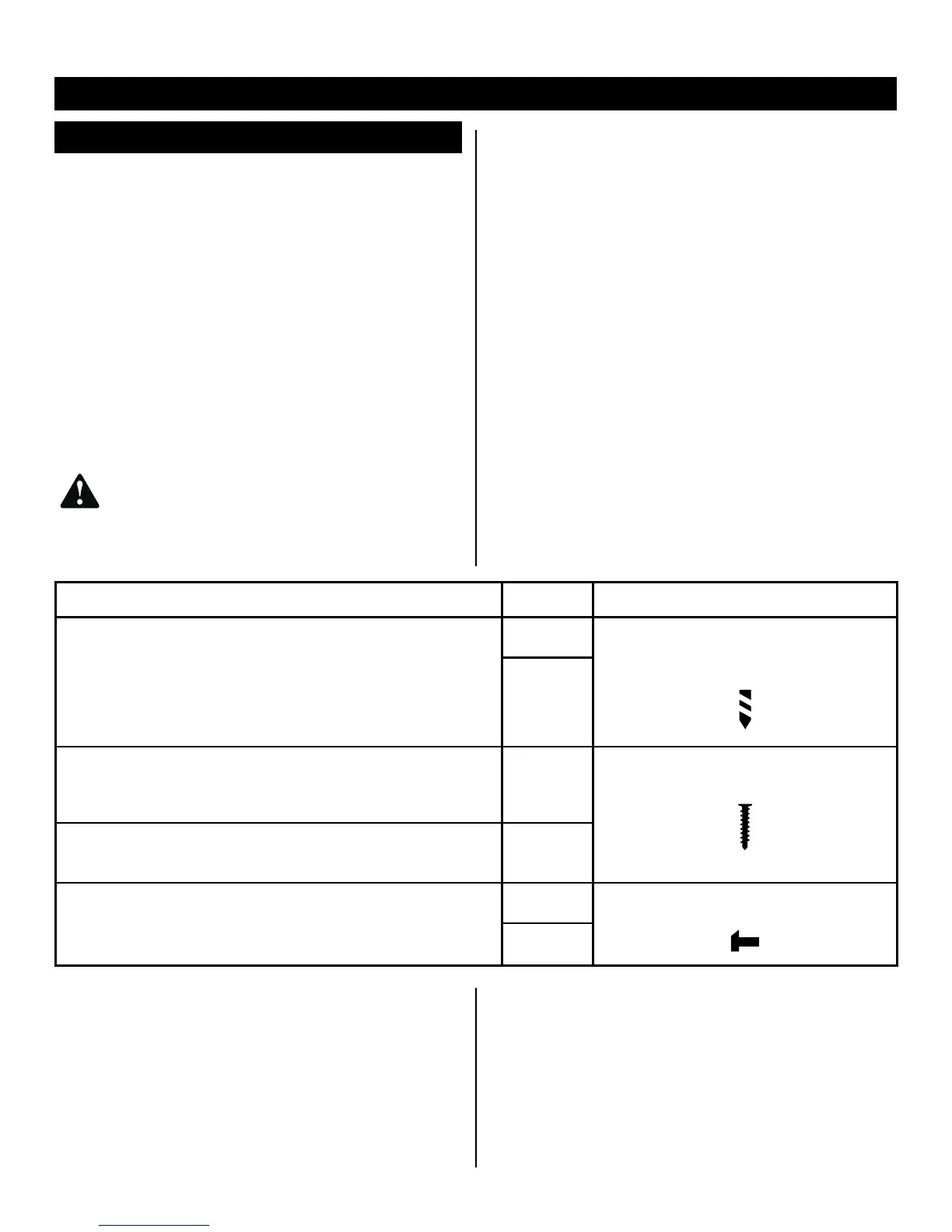
See Figure 6-7.
Using the chart below, choose correct speed and mode
the type of bit, fastener, and material you will be using.
Choose your
Choose the correct
Choose the correct
• Lag screws up to 9.5 mm dia. by 38.1 mm long
• Hole saw up to 50.8 mm
• Spade bits up to 38.1 mm
• Drill bits up to 12.7 mm
• Drilling into metal
• Concrete screws
1/LOW
DRILL MODE
(TORQUE ADJUSMENT NOT ACTIVE)
2/HIGH
• Drill bits up to 6.4 mm
• Deck or wood screws up to 63.5 mm long
• Self tapping screws
1/LOW
DRIVE MODE
• Deck or wood screws up to 63.5 mm long
• Small screws or delicate work that requires more control
2/HIGH
• Masonry bit up to 12.7 mm
1/LOW
HAMMER MODE
(TORQUE ADJUSMENT NOT ACTIVE)
2/HIGH
See Figure 8.
When using the drill-driver for various driving applications,
it becomes necessary to increase or decrease the torque
in order to help prevent the possibility of damaging
screw heads, threads, workpiece, etc. In general, torque
intensity should correspond to the screw diameter. If the
torque is too high or the screws too small, the screws
may be damaged or broken.
The torque is adjusted by rotating the torque adjustment ring.
The torque is greater when the torque adjustment ring
is set on a higher setting. The torque is less when the
torque adjustment ring is set on a lower setting.
The proper setting depends on the type of material and
the size of screw you are using.