15
ASSEMBLY
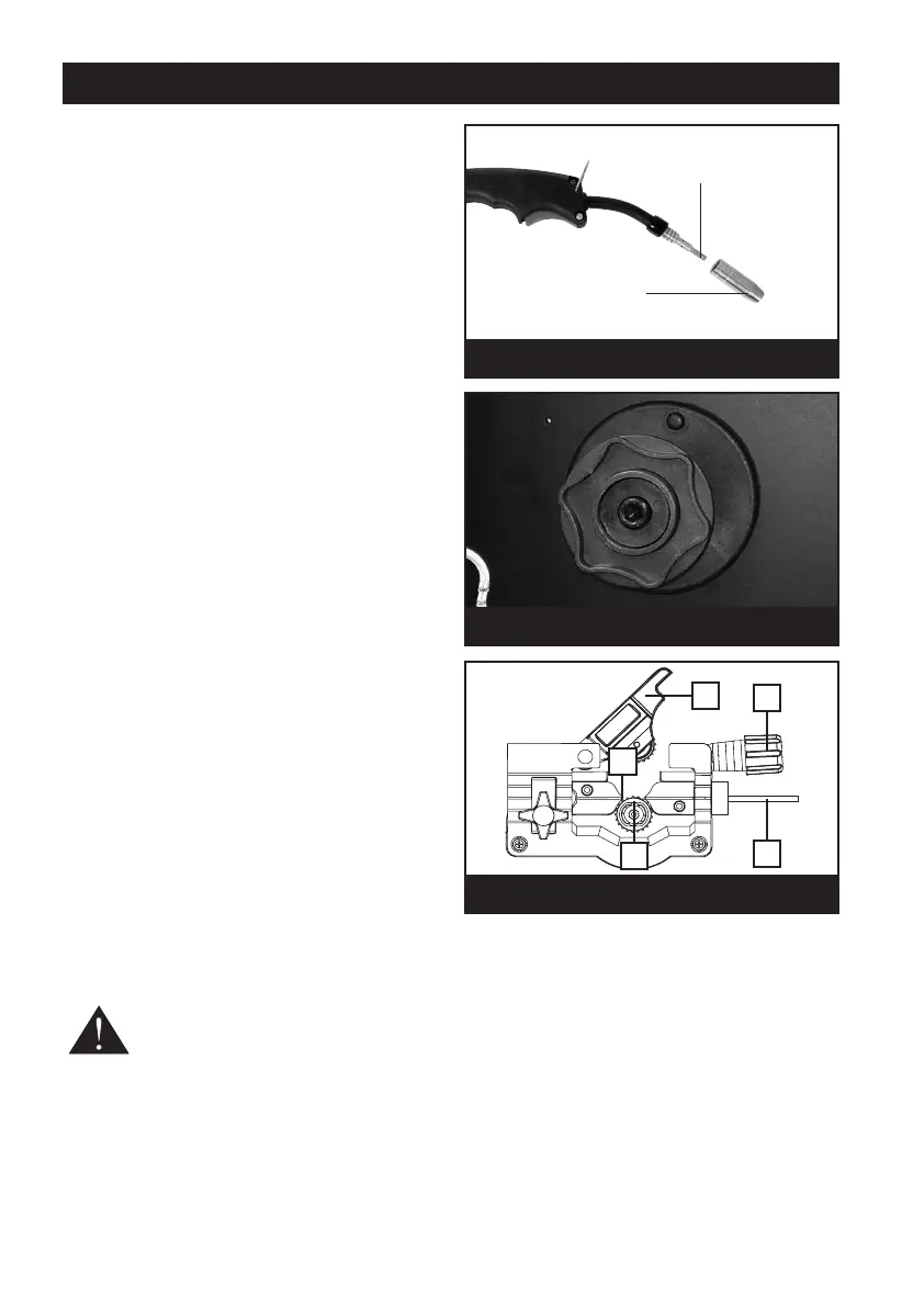
INSTALLING THE WELDING WIRE
U
nscrew the shroud from the end of the torch then
unscrew the contact tip (Fig.4).
O
pen up the side cover of the welder. If the wire
spool is mounted on the spool holder, it needs to
b
e removed in order to remove the plastic wrapper.
To do this, proceed as follows:
Unscrew and remove the plastic knob , followed by
the spring and collar from the hub, Fig.5.
Remove the plastic wrapper then slide the spool
back over the hub, ensuring that it sits snugly, and
replace the collar, spring and plastic knob,
tightening it sufficiently to allow the spool to rotate
smoothly but with a slight amount of braking
friction.
Do not over tighten as this will exert undue
pressure on the wire drive motor and may cause
serious damage.
TREADING THE WELDING WIRE (FIG.6)
Loosen the plastic knob (A) by turning it
anticlockwise, (this device maintains pressure on
the wire).
Pull, on the plastic knob, so that the screw rod
hinges out of its slot. This releases the pivoted
pressure roller bracket (C). Raise the bracket and
pull out any wire that has been left in the wire liner
(D), pulling it from the nozzle end of the hose.
Pull out the end of the wire from the rim of the
spool, taking care NOT to release it. The spool is
wound firmly and should remain this way. Ensuring
the wire is straight and not kinked in any way, clip
off the end cleanly, ensuring there are no burrs or
sharp edges. If it is remove the end using sharp
wire cutters.
Proceed to feed it through the guide tube (E), over
the groove on the roller (B), and into the wire liner
(D), by about 10 - 15 cm. Reposition the pressure
roller bracket (C, Fig.6) and plastic knob (A, Fig.6)
and tighten slightly.
CAUTION: Tightening the knob too tightly
will crush the wire and damage the wire
feed.
Fig. 4
Fig. 5
C
ontact tip
Shroud
Fig. 6
C
D
B
E
A