17
OPERATION
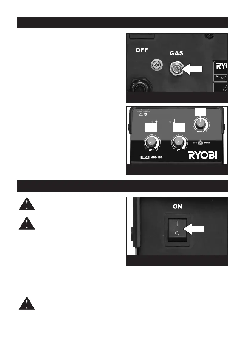
ATTACHING GAS BOTTLE AND REGULATOR
F
it a suitable regulator and gas supply tube onto
your gas bottle (Please note; regulator and gas
b
ottle not supplied). Attach the other end of your
g
as supply tube onto the gas pipe
attachment point on the back of the welder
(Fig.10).
Note: shielding gas is not required when using flux
cored welding wire.
ADJUSTING THE GAS FLOW
Turn the control knob on your gas regulator until
the required gas flow is achieved. We recommend
20 cfm.
ADJUSTING THE OUTPUT (FIG.11)
Set the amperage using the current control dial
(11.1), the voltage using the voltage control knob
(11.2) and the wire feed control dial (11.3) located
on the front panel, switching from one setting to
another adjusts the output and wire speed. On thin
materials use a low setting through to a higher
speed for thicker materials. Welding on thick
materials will significantly reduce the duty cycle of
the welder.
Fig. 10
Fig. 11
11.1
11.2
11.3
MIG WELDING
WARNING! If you have no welding
experience, we recommend you seek
training from an experienced person.
CAUTION: This manual is a basic guide
to welding. We recommend you
purchase a good quality publication on
welding or if you have internet access visit one of
the numerous welding related web sites to be able
to use the welding power supply to its full potential.
IMPORTANT! It is VITAL that the workpiece is
perfectly clean at the point of weld. Any coating,
plating or corrosion MUST be removed, otherwise
a good weld will be impossible to achieve.
Connect to the mains supply and press the On/Off
switch to the ON position (l) to stop the machine
press the switch to the OFF position (0). Fig.12.
WARNING! Always wear a full face
mask, welding gloves and protective
clothing. Wear goggles while chipping
slag.
Do not switch on the power supply until you are
ready to start welding. Practice welding on a piece
of scrap material.
The workpiece must be prepared correctly and the
area must be free from dirt, grease, oil, paint and
rust. Position the earth clamp as close to the
welding point as possible ensuring there is good
contact.
Fig. 12