18
MIG WELDING
Set the correct gas flow (when required),amperage
o
utput and voltage output for the material you are
welding.
T
he gas shield required will be either CO2 or Argon
or a mix of CO2 & Argon. Use the correct gas
(
when required) for the material to be welded.
When welding outside it may be necessary to
create a windbreak as a break down in the gas
shield can result in a poor weld.
Important: If you are welding on a vehicle
disconnect the vehicles battery or fit an electronic
circuit protector.
Position the tip about 6mm from the material to be
welded, hold the face mask in front of your face
then press the trigger on the torch. When the arc
strikes move the torch along the workpiece.
Maintain a steady gap between the end of the
contact tip and the workpiece. Maintain this
distance as constantly as possible during the weld.
The position of the welding rod is critical to obtain
the best result and achieve a good quality bead.
The torch should be positioned 75° horizontally and
35° vertically. Make sure the gas shroud remains
clear of spatter as a build up of spatter will reduce
the flow / effect of the gas shield. Keep the contact
tip clean to ensure smooth unrestricted wire feed.
The use of an anti-spatter spray will help to ensure
a good result.
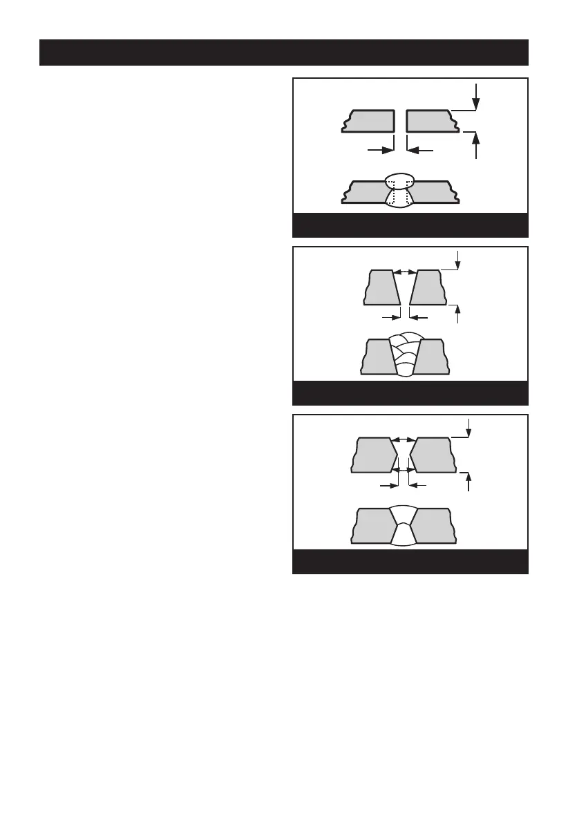
When welding material up to 7mm in thickness
place the pieces 2-3mm apart, run the welding
bead along the join. A second bead can go along
the underside for extra strength (Fig.13).
When welding material from 7mm to 30mm thick
prepare the material as shown in Fig.14 filling up
the space with several layers of weld.
When welding together material over 30mm in
thickness prepare the material as shown in Fig.15
filling up the space with several layers of weld.
Disconnect the welder from the mains power
supply before changing or removing wire reels. Use
pliers to move the welded pieces as they will be
extremely hot.
Note: As MIG welding is an aquired skill, it is
strongly advised that, if you are not fully familiar
with this type of welding, you practice on a piece of
material with the same characteristics as that of
your workpiece until you are satisfied with the
result, and you have fine tuned your welder to
produce a satisfactory weld.
One of the problems experienced with novice
welders, is the welding wire sticking to the contact
tip. This is as a result of the wire feed speed being
too slow. It is always better therefore to start with
too high a speed, and back off slightly, to avoid the
possibility of the wire welding itself to the tip. This is
the reason position 6 is recommended for start up.
The Wire Feed control is for fine tuning the wire
speed. The speed of wire delivery will increase
automatically as the current is increased.
Therefore, once the ideal speed is achieved, by
fine tuning, it should not be necessary to adjust this
control when the welding current is changed.
Fig. 13
Fig. 14
7
mm
60º
Fig. 15
2-3mm
>30mm
2-3mm
1
2
4
3
5
6
60º
>30mm
2-3mm