21
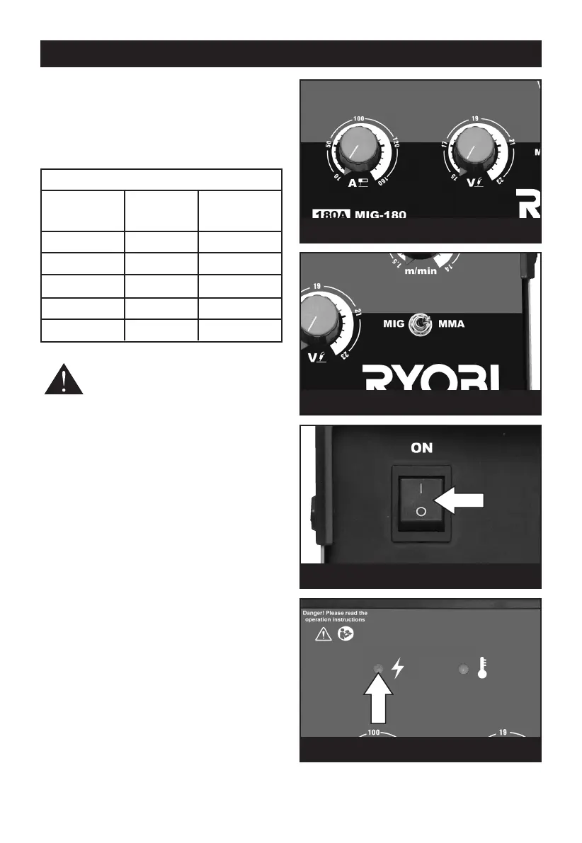
Set the amperage and voltage (see Table 1) by
a
djusting the regulators (Fig.17) until the desired
setting is reached.
T
he chart below is an indicator of the electrode
diameter and the corresponding welding current.
T
his is intended as a guide only.
WARNING! Always wear a full welding
mask, welding gloves and protective
clothing. Wear goggles while chipping
slag.
Do not switch on the power supply until you are
ready to start welding. Practice welding on a piece
of scrap material.
Connect to the mains supply. Press the MIG/MMA
switch to MMA mode, Fig.18. Press the On/Off
switch (Fig.19) to the ON position (l) The power
indicator lamp on the front panel (Fig.20) will
illuminate. To stop the machine, press the On/Off
switch to the OFF position (0).
Note: If the machine stops at any time and the
thermal cut out indicator on the front panel
illuminates, the thermal cutout has intervened.
This indicator will turn on when the machine is
overheated and the output has been disabled. This
normally occurs when the duty cycle of the
machine has been exceeded. Leave the machine
on to allow the internal components to cool. When
the indicator turns off, normal operation is again
possible.
MMA WELDING
Fig. 17
Fig. 18
Fig. 19
Table 1
Electrode Material Welding
size (mm) thickness current (A)
(mm)
1.6 1 - 1.6 25 - 40
2.0 1.6 - 2.6 40 - 70
2.5 2.6 - 4.0 60 - 100
3.2 3.0 - 5.0 80 - 130
4.0 5.0 - 7.0 130 - 170
Fig. 20