Deutsch (Übersetzung der originalen Anleitungen)
27
English (Original instructions)
■ Blade with cover
■ Shoulder harness (RBC254SBSO only)/ Shoulder
strap (RBC254SESO only)
■ Operator’s manual
■ Figure sheet
■ Nut
■ Washer
■ Engine oil
■ Combination wrench
■ Wrench
WARNING
If any parts are damaged or missing, do not
operate this tool until the parts are replaced.
Failure to heed this warning could result in
serious personal injury.
WARNING
Do not attempt to modify the product or create
accessories not recommended for use with the
product. Any such alteration or modification is
misuse and could result in a hazardous condition
leading to possible serious personal injury.
WARNING
To prevent accidental starting that could cause
serious personal injury, always disconnect the
engine spark plug wire from the spark plug when
assembling parts.
WARNING
Never attach or adjust any attachment while
power head is running. Failure to stop the engine
may cause serious personal injury.
WARNING
Be certain the knob is fully tightened before
operating equipment; check it periodically for
tightness during use to avoid serious injury.
ATTACHING THE HANDLE
(Fig. 2a)
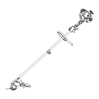
RBC254SBSO
■ Remove the bolts and clamp.
■ Place the handle bar.
NOTE: The throttle trigger must be mounted to the
operator's right side.
■ Replace the bolts and clamp.
■ Adjust the handle bar for best operator control and
comfort.
■ Use the wrench to tighten the bolts securely.
RBC254SESO
■ Remove the securing screws and clamp from the front
handle.
■ Align the hooks on the clamp into upper shaft slot.
■ Install the front handle onto the upper shaft.
NOTE: The front handle should tilt slightly towards the
operator when correctly fitted.
■ Place the securing bolts through the front handle and
securely tighten them into the captive nuts on the
bracket.
NOTE: Do not attempt to remove the locks on the
bracket, the locks limit the upper position of the front
handle.
ATTACHING THE BLADE GUARD AND GRASS
DEFLECTOR
Blade guard
(Fig. 2b)
■ Attach the blade guard to the mounting bracket and
align the screw holes on the blade guard to the screws
on the mounting bracket.
■ Using the combination wrench, tighten all two screws
securely.
WARNING:
– The blade deflector should remain fitted to the product
at all times.
Grass defl ector
(Fig 2b)
■ To attach the grass deflector to the blade guard, align
the 3 screws on the grass deflector to the screw holes
on the blade guard.
■ Use the combination wrench to tighten the screws
securely.
NOTE: When using the string head, the grass deflector
must be attached to the blade guard.
ATTACHING THE POWER HEAD TO THE TRIMMER
ATTACHAMENT (FIG. 2C)
WARNING
If any parts are damaged or missing, do not
operate this tool until the parts are replaced.
Failure to heed this warning could result in
serious personal injury.
■ Loosen the knob on the coupler of the power head

 Loading...