MOUNTING THE ROUTER
17
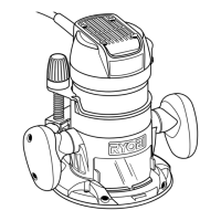
Fig. 20
See Figure 20
8. Turn the router table upside-down. Align the three
locating pins in the bottom of the table top as shown.
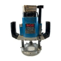
See Figure 21
9. Place clamp (T), swivel piece (S), washer (AK), and
knob (M) on screw (AB) as shown. Leave assembly
loose to allow clamp to be adjusted. Repeat the above
procedures for the 3 remaining clamps.
Fig. 21
M
AK
S
T
AK (4)
AB
AB (4)
AQ (4)AL (4)
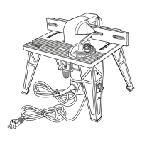
Fig. 19
AB
AL
AQ
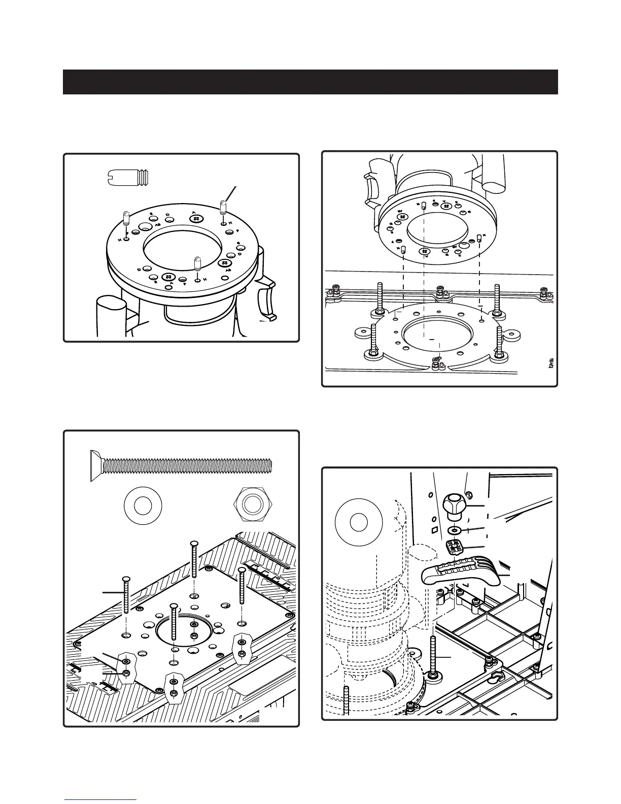
See Figure 18
6. Screw the three locating pins (V) into nuts on adapter
plate from top side at hole position H.
See Figure 19
7. Insert the 4 countersink screws (AB) through holes in table
top. Tighten securely with the 4 hex nuts (AQ) placing the
4 washer (AL) between the nuts (AQ) and the tabletop.
Use an adjustable wrench or a combination wrench
(size 10 mm) to tighten the nuts.
V
V (3)
Fig. 18