11 — English
UNPACKING
This product requires assembly.
Carefully cut the box down the sides then remove the
machine and any accessories from the box. Make sure
that all items listed in the loose parts list are included.
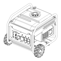
NOTE: This machine is heavy and requires a minimum of
two people to lift. To avoid back injury, lift with your legs
and not your back.
WARNING:
Do not use this product if any parts in the Loose Parts List
are already assembled to your product when you unpack
it. Parts on this list are not assembled to the product by
the manufacturer and require customer installation. Use
of a product that may have been improperly assembled
could result in serious personal injury.
Inspect the unit carefully to make sure no damage oc-
curred during shipping.
Do not discard the packing material until you have carefully
inspected and satisfactorily operated the product.
If any parts are damaged or missing, please call
1-800-525-2579 for assistance.
WARNING:
If any parts are damaged or missing do not operate
this product until the parts are replaced. Use of this
product with damaged or missing parts could result in
serious personal injury.
WARNING:
Do not attempt to modify this product or create acces-
sories not recommended for use with this product. Any
such alteration or modification is misuse and could result
in a hazardous condition leading to possible serious per-
sonal injury.
WARNING:
Do not attempt to operate the generator until assembly
is complete. Failure to comply could result in possible
serious personal injury.
LOOSE PARTS LIST
See Figure 3.
The following items are included with the generator:
Key
No. Description Qty.
1 Wheel Cap ...........................................................2
2 Axle ......................................................................2
3 Wheel ...................................................................2
4 Washer .................................................................2
5 Hitch Pin ..............................................................2
6 Bolt ......................................................................4
7 Spring Washer .....................................................4
8 Foot Assembly .....................................................2
9 Engine Lubricant ..................................................1
10 Handle Lock Pin ..................................................1
11 Lanyard ................................................................1
12 Handle .................................................................1
13 Wrench ................................................................2
14 Shoulder Bolt .......................................................2
Operator’s Manual (not shown) ...........................1
NOTE
: Do not put fuel or lubricant in the generator before
installing the feet, frame support, wheels and handle.
INSTALLING FEET
See Figure 4.
Locate the following items:
2 foot assemblies
4 spring washers
4 bolts
1 wrench, 8 mm
Align holes in bracket with holes in generator frame cross
brace.
Insert a bolt through a spring washer and then through
each hole in the cross brace and foot assembly bracket
as shown.
Tighten one full turn past snug.
Repeat with remaining foot.
INSTALLING THE WHEELS
See Figure 5.
Wheels are provided to assist in moving the generator to
the desired location and should be installed on the same
side as the handle.
Locate the following items:
2 axles
2 hitch pins
2 washers
2 wheels
2 wheel caps
ASSEMBLY