10
TWO-WHEEL TRACTOR CONTROLS
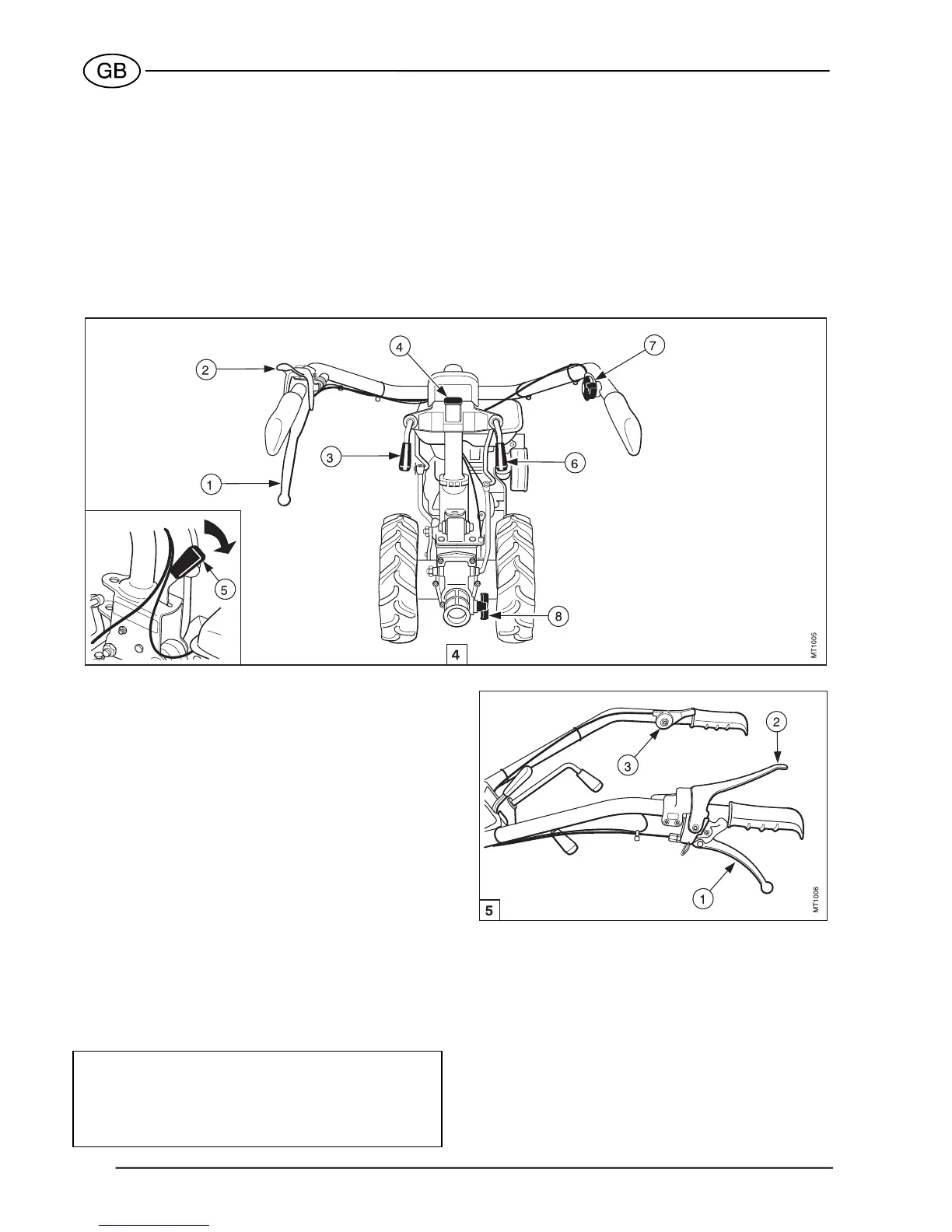
See fig.4.
1. Clutch lever.
2. Engine stop lever.
3. Gear lever. (Note 2)
4. Handlebar vertical lock release lever.
5. Handlebar sideway lock release lever.
6. PTO control lever. (Note 1).
7. Throttle control lever.
8. Attachments instant adaptor.
NOTE 1: When the machine is fitted with front-
mounted attachments, this lever becomes
the gear lever.
NOTE 2: When the machine is fitted with front-
mounted attachments, this lever becomes
the PTO control lever.
OPERATING THE CONTROLS
Clutch lever
(See fig. 5)
− Lever (1) pulled up: clutch disengaged.
− Lever (1) released: clutch engaged.
Engine stop lever
See figure 5.
− Lever (2) pressed down: engine running.
− Lever (2) released: engine stopped.
Throttle control lever
(See figure 5)
− Lever (3) in up position: engine at idle.
− Lever (3) in down position: max engine rpm.
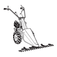
Gear lever (two-wheel tractor configuration)
CAUTION
When using the machine as a motor mower, the han-
dlebars must be rotated through 180. The gear and
PTO control levers therefore interchange position.
See page 11 for details.
Use the gear lever as shown below (see fig. 6):
a. Turn the throttle control lever (1) to idle position.
b. Pull up clutch lever (2).
c. Move the gear lever (refer to fig. 6, item 3) to the
required position (see the plate illustrated in detail
A), and release it as soon as the gear is engaged.
d. Gradually release the clutch lever while accelerat-
ing the engine.
e. To disengage gear, pull up the clutch lever (2) and
move gear lever (3) to the neutral position.