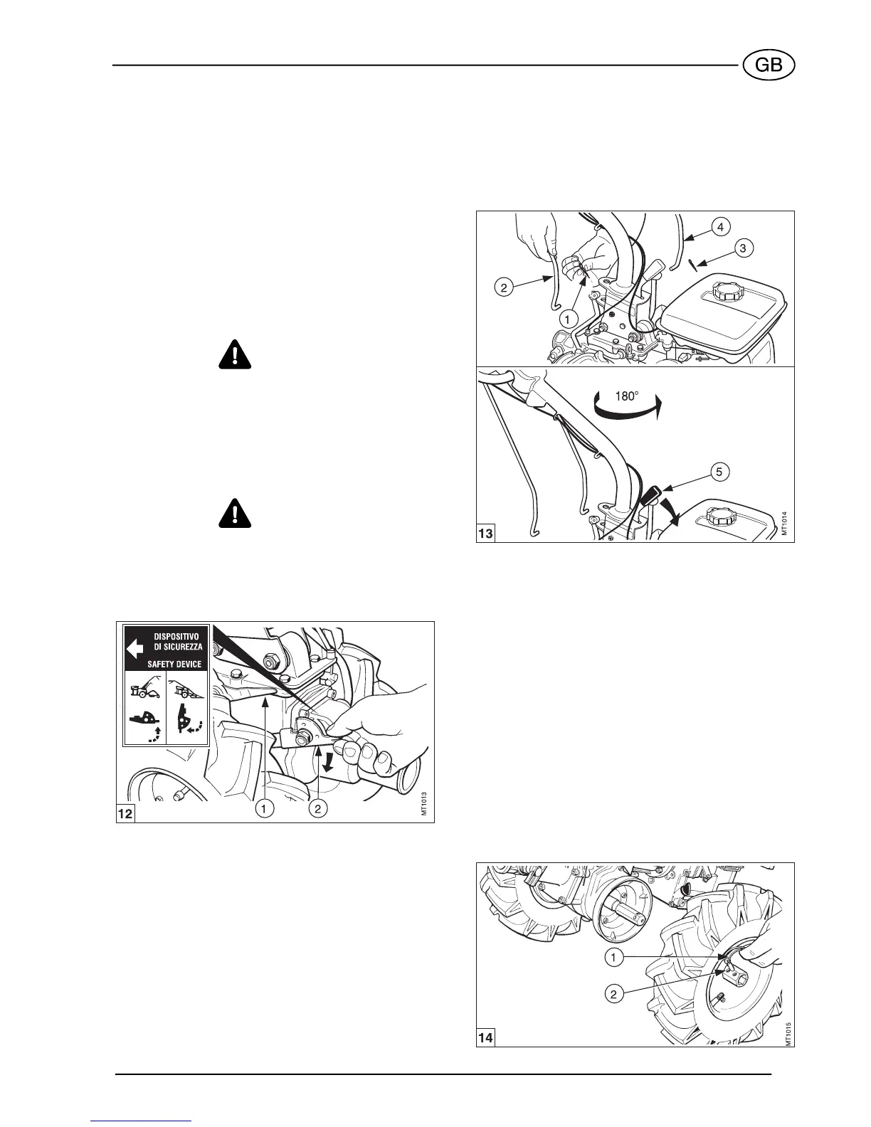
13
FITTING FRONT-MOUNTED
ATTACHMENTS
Before fitting a front-mounted attachment (cutter bar
mower, rotary mower, snow thrower, etc.), adjust the
reverse speed safety device as required, reverse the
handlebars and the wheels.
CAUTION
SUPER SMART Diesel model does not allow the use
of front attachment.
SAFETY DEVICE
Set the reverse speed safety device in the correct po-
sition as regards the direction of travel (see fig. 12).
WARNING
Before using the machine, check that is in correct po-
sition.
a. Move the lever (1) to give free movement of the
safety device.
b. Push the safety device lever (2) down (see the
plate showing the "motor mower") to allow reverse
gear to be engaged.
WARNING
When converting the machine back into the two-
wheel tractor version, to fit the rotary tiller, engage the
safety device by proceeding in the opposite way to
the way described above (see the plate showing the
"two-wheel tractor”).
REVERSING THE HANDLEBARS
Rotate the handlebars through 180° to operate the
machine in the changed direction of motion. Proceed
as follows:
a. Remove the pin (see fig. 13, item 1) locking the
gear control rod (2).
b. Remove the pin (3) locking the power take-off rod
(4).
c. Squeeze the lever (5) and rotate the handlebars,
180° anticlockwise; release the lever (5) and lock
the handlebars.
d. Connect again the gear (2) and PTO (4) control
rods to the corresponding control levers and se-
cure with pins (1) and (2).
NOTE
While reversing the handlebars, make sure that the
cables do not become tangled or caught.
REVERSING THE WHEELS
Every time you use a front-mounted attachment, the
wheels must be interchanged to keep the tread pat-
tern pointing in the right direction. Simply remove
each wheel from its hub and install it on the opposite
hub. An arrow on the sidewall of the tire indicates the
correct direction of rotation (see fig. 14).
a. Remove the pins (1).
b. Remove the wheels and put the right wheel on the
left and vice-versa.
c. Replace the pins (1).
Adjusting the track
Two different track sizes can be obtained as a result
of the double holes in the hub cap (2). To do this, fix
the wheel by means of the plug (1), which is inserted
into the desired hole.