INTEGRA/-S/-G/-GS User Manual INSTALLATION
SAF Tehnika JSC
M8x160 and M8x130 threaded rods
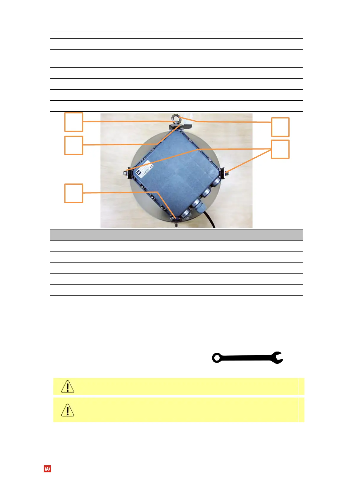
Clamps for housing and pipe interconnected with three M8x1.25x16 hex flange bolts [1]
and an eye screw for horizontal alignment [2]
Six M8x1.25 hex flange nuts
One hex flange bolt M8x1.25x20
Parts of Integra/Integra-G FODU
The numbers of the mounting bracket and Integra/Integra-G FODU parts in the next sections
will be mentioned in square brackets [ ].
Changing the polarization of Integra/Integra-G FODU and antenna
Tools required: 13mm (0.512”) wrench (comes in the
package)
The default polarization for licensed frequency band radios is vertical.
Integra series 17/24GHz FODUs should be installed in opposite polarizations.
By default, Integra series 17/24GHz FODU radios are shipped with opposite polarizations
pre-installed for low and high side units.
 Loading...