INTEGRA/-S/-G/-GS User Manual INSTALLATION
SAF Tehnika JSC
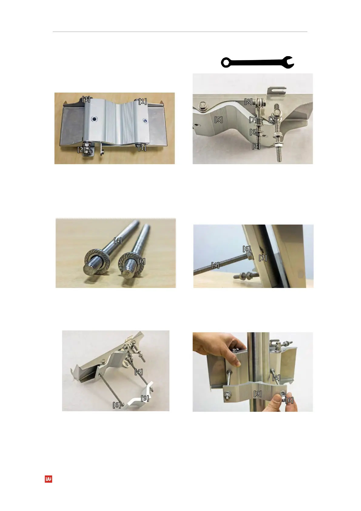
Assembly procedure
Tools required: 13mm (0.512”) wrench (comes in the
package)
Using a 13mm wrench slightly loosen three hex
flange bolts [1] and hex flange bolt, nut, and eye
screw [2] interconnecting clamps for housing
and pipe [5].
Attach vertical alignment eye screw [3] to clamps for
housing and pipe [5] using hex flange bolt [8] and
screw on one hex nut [7] and two hex flange nuts [6].
Make sure that both eye screws are positioned as
shown in the image (turned to the back side of the
clamps). The gap between each two flange nuts on
eye screws should be 15..20mm (0.6..0.8 in.). Do not
tighten both hex flange bolts [8] and [2].
Screw one hex flange nut [6] on each of the
threaded rods [4]. Note that flange nuts should
be screwed on exposing approx. 20mm (0.8 in.)
of threaded rods.
Insert both threaded bolts into two available holes of
the mounting clamp. Put hex nuts [7] on the other side
of the clamp and screw on the threaded bolts until it is
visible from the other side of the clamp no more than
2mm. Tighten hex flange nuts [6] with torsion 20...25
N·m.
Attach the mounting bracket clamp [9] on the
longest threaded rod [4] as shown in the picture
and afterward screw on the remaining two hex
flange nuts [6] on both threaded rods. No parts
should remain unassembled.
Bracket clamps in the following position
support mast ∅ 55..120mm. Reversing clamps
allow support of smaller masts ∅ 25..75mm.
Unscrew the hex flange nut [6] from the shortest
threaded rod [4]. Make sure that hex flange nuts on the
longest threaded rod are not too far; otherwise, adjust
the nut’s position accordingly. Put another end of the
mounting bracket clamp [9] on the free threaded rod
and screw on the hex flange nut.
 Loading...