2322
4.4 Mode 4: Testing and adjusting AUX-connection
5. Optional features
5.1 AUX-connection (optional)
Safera PCU6.3 and PCU6.1 power control units Ⓒ are equipped with two auxiliary out-
put signals AUX1 and AUX2 compatible with most automation and security systems.
They can be used to send real-time status information of the stove guard.
5.1.1 Electrical speciications
• Optoisolated and potential-free
AUX-outputs: no galvanic connec-
tion between the Safera system and
the automation system.
• When the AUX outputs are active
(ON), the optoisolator’s output tran-
sistors will be held in conducting
mode, thus enabling current low
from IN to OUT. This connection can
be used exactly as a relay’s contact,
however the direction and amount
of the current low must be con-
trolled as speciied below. If neces-
sary, the output states can also be
inversed (see chapter 5.1.6).
• Maximum IN-OUT voltage is 24 VDC.
• Maximum IN-OUT current is 10 mA.
• Only DC voltage between IN-OUT,
no AC is permitted!
5.1.2 Coupling AUX-wire to the
power control units PCU6.X
Connect AUX-
wire to the
screw terminal.
Route the AUX-
wire through
the strain relief.
Mount the cover of the power
control unit Ⓒ with the screws and
ensure that the AUX-wire is properly
placed on the strain relief.
2
4
x 4
1
3
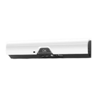
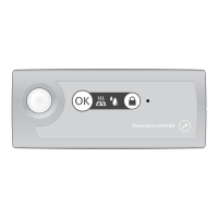
When the indicator light ❹ is blinking white (normal AUX-mode) or a blinking red
(inversed AUX-mode, see chapter 5.1.), you may:
• Test the AUX-connection:
• Toggle the AUX1 output ON/OFF by pressing the Adjustment button ❶
• Toggle the AUX2 output ON/OFF by pressing the Adjustment button ❷
• Toggle AUX-mode to "normal" or "inversed" by pressing and holding the Adjust-
ment button ❶ for ive seconds:
• Normal AUX-mode selected: indicator light ❹ blinks white
• Inversed AUX-mode selected: indicator light ❹ blinks red
To exit manual adjustment mode 4, press OK button
❸ once. The stove guard and
AUX signals will return to their normal operating state.
 Loading...