May 2016
Evolion
®
3.9 kWh
Installation and operation instruction sheet
1. Introduction
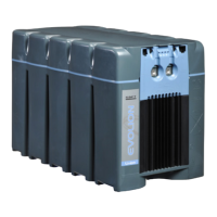
The Evolion
®
is a Li-ion battery system that includes large format Li-ion cells and
necessary electronics for automatic interruptions or regulated operations when un-safe
limit is exceeded and detected.
This sheet is a quick start guide. It describes how to install and operate the Evolion
®
in a legacy battery mode, i.e., with no RS485/Modbus communication connected.
Within this sheet, the necessary tasks are noted with
Ev#’s
and they are in order that
they should be conducted. Use the Evolion
®
3.9 kWh historical data sheet (included)
for records. Make sure to read the Evolion
®
3.9 kWh Installation and Operation User
Manual (UM), the Evolion
®
3.9 kWh Technical Manual (TM) and the Evolion
®
Toolbox
Software User Manual (CM). Check with your local Saft Representative for more details.
Ev6
Check for a maximum of
2 V difference allowed
between modules that will
operate on the same bus.
Figure 1
Figure 4
If modules have more than 2 V difference
equalizing the Evolion
®
modules is
necessary, refer to the Evolion
®
UM.
Ev7
For modules that will
operate on the same bus,
set each with a unique
Node ID, manually between
1 to 4 or using the Evolion
®
Toolbox Software.
Figure 6
(manual)
or
Evolion
®
CM
(software)
The Evolion
®
can be installed and
operated in Network Telecommunication
Facilities including un-manned OSP. The
Evolion
®
can be placed on shelves or in
battery compartments with the following
characteristics.
• IP54 (NEMA3) or higher
• -40°C to 75°C (-40°F to 167°F)
• 95% RH max. (non-condensing)
• Up to 3000 meters (9843 feet)
• No blocking the heat sink and vent ports
• Right side up or sideways
Ev8
Connect the Evolion
®
modules.
Figure 8
Figure 9
Ev9 Power ON
Figure 10
8. Operation/Maintenance
The Evolion
®
provides un-interrupted standby
power anytime the AC power supply is
OFF. Continue trouble free operation in
accordance with these instructions.
The Evolion
®
requires no maintenance,
but periodically checking it during other
site routines is recommended.
• LED state (Table 3 and 9.
Troubleshooting)
• SOC and SOH (Table 2)
• Heat sink area un-obstructed
• Clean any excessive dirt build-up using a
nonmetallic brush or a dry or damp cloth.
• Do not use any cleaning solvents or soaps.
• Do not immerse, bathe or hose off the
Evolion
®
.
9. Troubleshooting
When the Evolion
®
is in service, observe
the LED's. See Table 3 for operation
LED state.
4. Unpacking and Inspection
The Evolion
®
is packaged in accordance
with UN3480 Class 9 Group 2. See
Figure 1 for lifting instructions.
Ev1
Check that all items are
received.
Table 1
If items were not received or if anything
was damaged do not install the module
and contact your local Saft representative.
Ev2
Study Evolion
®
features. Figure 3
Ev3
Check the state after
receiving and before
storage or installation.
Figure 1
Figure 4
Table 2
Always keep the Evolion
®
module and its
kit in its original packaging, together.
5. Storage
Store the battery in its original packaging.
• 15°C to 35°C (59°F to 95°F).
• No direct sunlight, rain or flooding
• Up to 1 year without refreshing charge
Ev4
After 6 months, check the
state once per month in
storage.
Table 2
Figure 4
IMPORTANT: Never leave the Evolion
®
ON when it is not in use. The internal
electronics will self-discharge the cells
to a low voltage alarm level which may
render the module un-usable.
6. Transportation
Follow the necessary transportation
rules for Li-ion batteries by consulting
with your company’s standard practice
and your local transportation regulations.
• Use the original packaging or equivalent.
• Secure the Evolion
®
in place
• The Evolion
®
must be OFF.
7. Installation
Before installing, make sure the right
number of Evolion
®
you will connect to
one bus is properly sized. Consult with
your local Saft Representative or consult
with the Evolion
®
TM.
Ev5
Size the proper number
of Evolion
®
to connect to
one bus.
Evolion
®
TM
Before installing, double check the state
of each Evolion
®
.
2. Safety
Misusing the Evolion
®
may cause an event
like cell venting, overheating or igniting.
Read these instructions fully before
installing and operating the Evolion
®
.
Do not short-circuit the power
terminals.
Do not reverse connect the power
cables to the charger.
Do not disassemble the unit.
Do not drop the unit.
Do not immerse the unit.
Do not expose the unit to fire or
temperature higher than 80°C
(176°F).
Connect only to telecom power
systems/rectifiers with a maximum
rated output of 60 V.
Refer to the Battery Information
Sheet or BIS (included) for
emergency response procedures
and personal protective equipment
in case of an abnormal event.
If smoke is emitted from the
module, stay clear of the smoke and
evacuate the area immediately.
For normal handling and operation
according to this installation and
operation sheet, no personal
protective equipment is required.
3. Tools
These tools are needed and are not
provided.
LED
state
Refer to
D Evolion
®
TM, Appendix E
E Evolion
®
TM, Appendix E; Figure 11
IMPORTANT: The Evolion
®
must
be re-charged within 2 weeks after
Alarm #36 was activated or the
module may be rendered useless.
G Figure 11
Tool Use
Voltage and fuse continuity
Front cover removal/
replacement
Grounding point screw
Power and fuse terminals
External case notations
BMST reset button