UAIS DEBEG 3400, Electronics Unit
ED3047G142 / 08 (2004-06)
Technical Manual
List of Figures
t_ue_eAV.fm / 21.06.04
7
List of Figures
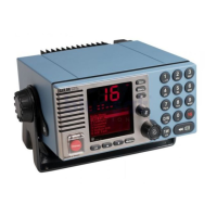
Fig. 2-1 UAIS DEBEG 3400 with DCU DEBEG 3401 . . . . . . . . . . . . . . . . . . . . . . . . . . . . . . . . . . . . . . . 14
Fig. 2-2 UAIS DEBEG 3400 in RADARPILOT 1000 systems . . . . . . . . . . . . . . . . . . . . . . . . . . . . . . . . 15
Fig. 2-3 UAIS DEBEG 3400, SAM Electronics 1000 series systems (NACOS xx-4) . . . . . . . . . . . . . . 16
Fig. 2-4 UAIS DEBEG 3400 with CHARTPILOT stand-alone . . . . . . . . . . . . . . . . . . . . . . . . . . . . . . . . . 17
Fig. 2-5 UAIS DEBEG 3400 in NACOS xx-3 systems . . . . . . . . . . . . . . . . . . . . . . . . . . . . . . . . . . . . . . 18
Fig. 2-6 UAIS DEBEG 3400 in Radar 9xxx systems with RADARPILOT 1000 . . . . . . . . . . . . . . . . . . . 19
Fig. 2-7 UAIS DEBEG 3400 in Radar 9xxx systems . . . . . . . . . . . . . . . . . . . . . . . . . . . . . . . . . . . . . . . 20
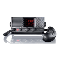
Fig. 2-8 UAIS DEBEG 3400 Electronics Unit . . . . . . . . . . . . . . . . . . . . . . . . . . . . . . . . . . . . . . . . . . . . . 21
Fig. 3-1 Cable inlet consisting of a hole with brackets . . . . . . . . . . . . . . . . . . . . . . . . . . . . . . . . . . . . . . 24
Fig. 3-2 Minimum distances for GPS and VHF Antenna . . . . . . . . . . . . . . . . . . . . . . . . . . . . . . . . . . . . 27
Fig. 3-3 Positioning of the VHF Antenna . . . . . . . . . . . . . . . . . . . . . . . . . . . . . . . . . . . . . . . . . . . . . . . . . 28
Fig. 3-4 Positioning of the GPS Antenna . . . . . . . . . . . . . . . . . . . . . . . . . . . . . . . . . . . . . . . . . . . . . . . . 29
Fig. 3-5 Minimum distances for the GPS Antenna from a Radar Scanner . . . . . . . . . . . . . . . . . . . . . . 29
Fig. 4-1 Block diagram of the AIS System . . . . . . . . . . . . . . . . . . . . . . . . . . . . . . . . . . . . . . . . . . . . . . . 33
Fig. 4-2 Principle of wiring for Ethernet LAN . . . . . . . . . . . . . . . . . . . . . . . . . . . . . . . . . . . . . . . . . . . . . . 35
Fig. 4-3 Block diagram of the Electronics Unit . . . . . . . . . . . . . . . . . . . . . . . . . . . . . . . . . . . . . . . . . . . . 36
Fig. 4-4 Interfaces of the DEBEG UAIS 3400 Electronics Unit . . . . . . . . . . . . . . . . . . . . . . . . . . . . . . . 37
Fig. 4-5 Internal coax wiring . . . . . . . . . . . . . . . . . . . . . . . . . . . . . . . . . . . . . . . . . . . . . . . . . . . . . . . . . . 38
Fig. 4-6 AIS Stand-alone with DCU and Gyro Interface 9401 . . . . . . . . . . . . . . . . . . . . . . . . . . . . . . . . 45
Fig. 4-7 AIS Stand-alone with DCU . . . . . . . . . . . . . . . . . . . . . . . . . . . . . . . . . . . . . . . . . . . . . . . . . . . . . 46
Fig. 4-8 Pilot Port, connector assignment, front view (pins) . . . . . . . . . . . . . . . . . . . . . . . . . . . . . . . . . . 47
Fig. 6-1 Cable connection for the interface monitoring Radar > AIS . . . . . . . . . . . . . . . . . . . . . . . . . . . 52
Fig. 6-2 Protocol Radar TxD . . . . . . . . . . . . . . . . . . . . . . . . . . . . . . . . . . . . . . . . . . . . . . . . . . . . . . . . . . 53
Fig. 6-3 Cable connection for the interface monitoring AIS > Radar . . . . . . . . . . . . . . . . . . . . . . . . . . . 54
Fig. 6-4 Protocol AIS TxD . . . . . . . . . . . . . . . . . . . . . . . . . . . . . . . . . . . . . . . . . . . . . . . . . . . . . . . . . . . . 55
Fig. 6-6 Suggestion for an update cable . . . . . . . . . . . . . . . . . . . . . . . . . . . . . . . . . . . . . . . . . . . . . . . . . 59
Fig. 6-8 Service Interface . . . . . . . . . . . . . . . . . . . . . . . . . . . . . . . . . . . . . . . . . . . . . . . . . . . . . . . . . . . . . 60
Fig. 6-9 Opening of the Electronics Unit housing . . . . . . . . . . . . . . . . . . . . . . . . . . . . . . . . . . . . . . . . . . 63
Fig. 6-10 Exchange of the Electronics Module . . . . . . . . . . . . . . . . . . . . . . . . . . . . . . . . . . . . . . . . . . . . . 64
Fig. 6-11 Position of the fan . . . . . . . . . . . . . . . . . . . . . . . . . . . . . . . . . . . . . . . . . . . . . . . . . . . . . . . . . . . 68
Fig. 9-1 Cable Diagram 1/6, connection to DCU DEBEG 3401 via Primary Display Port . . . . . . . . . . . 82
Fig. 9-2 Cable Diagram 2/6, connection to RADARPILOT 1000/NACOS xx-4 via Primary Display Port 83
Fig. 9-3 Cable Diagram 3/6, connection to CHARTPILOT, NACOS-xx4, RADAR / MULTIPILOT 1000 via
LAN . . . . . . . . . . . . . . . . . . . . . . . . . . . . . . . . . . . . . . . . . . . . . . . . . . . . . . . . . . . . . . . . . . . . . . . 84
Fig. 9-4 Cable Diagram 4/6, connection to CHARTPILOT stand-alone . . . . . . . . . . . . . . . . . . . . . . . . . 85
Fig. 9-5 Cable Diagram 5/6, connection to Radar 9xxx via Radar 9xxx AIS Interface (NACOS xx-3) .86
Fig. 9-6 Cable Diagram 6/6, connection to DCU DEBEG 3401 and Gyro Converter DEBEG 4901 . . . 87
Fig. 9-7 Connection Diagram 1/10, connection to DCU DEGEG 3401 . . . . . . . . . . . . . . . . . . . . . . . . . 88
Fig. 9-8 Connection Diagram 2/10, DCU connectors (alarm input, Primary Display Port, power supply) .
89
Fig. 9-9 Connection Diagram 3/10, connection to NACOS xx-4, RADAR/MULTIPILOT 1000 via Prim.
Displ. Port . . . . . . . . . . . . . . . . . . . . . . . . . . . . . . . . . . . . . . . . . . . . . . . . . . . . . . . . . . . . . . . . . . 90
Fig. 9-10 Connection Diagram 4/10, terminals at the Analog Interface . . . . . . . . . . . . . . . . . . . . . . . . . . 91
Fig. 9-11 Connection Diagram 5/10, connection to CHARTPILOT, NACOS, RADAR/MULTIPILOT 1000 via
LAN . . . . . . . . . . . . . . . . . . . . . . . . . . . . . . . . . . . . . . . . . . . . . . . . . . . . . . . . . . . . . . . . . . . . . . . 92
Fig. 9-12 Connection Diagram 6/10, connection to CHARTPILOT stand-alone systems . . . . . . . . . . . . 93
Fig. 9-13 Connection Diagram 7/10, connection to Radar 9xxx via Radar 9xxx AIS Interface (NACOS xx-3)
94
Fig. 9-14 Connection Diagram 8/10, terminals at the Gyro Converter Unit DEBEG 4901 . . . . . . . . . . . 95
Fig. 9-15 Connection Diagram 9/10, connection to DCU DEBEG 3401 and Gyro Converter Unit DEBEG
4901 . . . . . . . . . . . . . . . . . . . . . . . . . . . . . . . . . . . . . . . . . . . . . . . . . . . . . . . . . . . . . . . . . . . . . . 96
Fig. 9-16 Connection Diagram 10/10, terminals of the Radar 9xxx AIS Interface . . . . . . . . . . . . . . . . . . 97
 Loading...