R5 Series
Connecting Procedures:
1. Tighten the lock screws on positive and cathode connector.
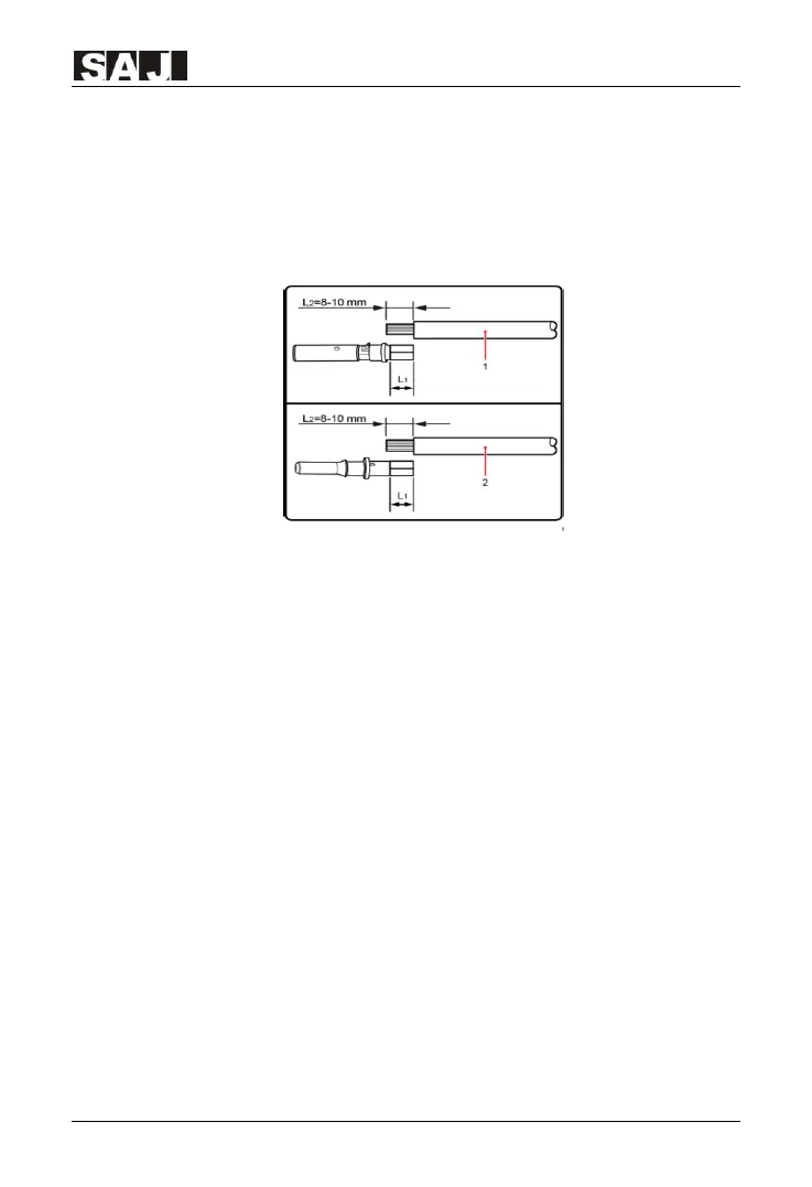
2. Use specified strip tool to strip the insulated enclosure of the positive and cathode
cables with appropriate length.
1.Positive cable 2. Cathode cable
Figure 5.13 Connecting cables
3. Feed the positive and cathode cables into corresponding lock screws.
4. Put the metal positive and cathode terminals into positive cable and cathode cable
whose insulated enclosure has been stripped, and crimp them tightly with a wire
crimper. Make sure that the withdrawal force of the pressed cable is bigger than
400N.
5. Plug the pressed positive and cathode cables into relevant insulated enclosure, a
“click” sound should be heard or felt when the contact cable assembly is seated
correctly.
6. Fasten the lock screws on positive and negative connectors into respective
insulated enclosure and make them tight.
7. Connect the positive and cathode connectors into positive and negative DC input
terminals of the inverter, a “click” sound should be heard or felt when the contact
cable assembly is seated correctly.
 Loading...