VIII. DESCRIPTION OF THE FUNCTIONAL OPERATION OF THE
SALCOR MODEL 3G UNIT ALARM BOARD
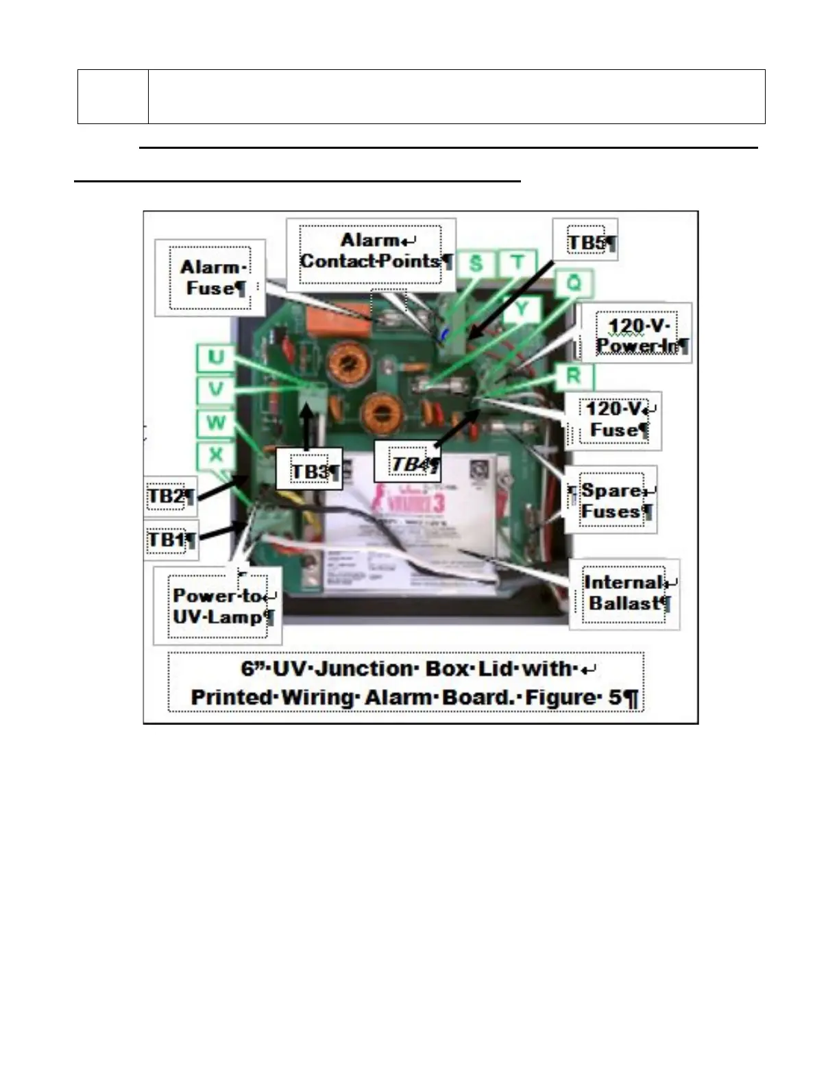
The 120 VAC power is fed into the junction box and connected to the Printed
Wiring Alarm Board at points Q & R of terminal block TB4. The power is then routed
through the fuse at point Y and on to points U and V of terminal block TB3. The ballast
wires are connected to points U and V of terminal block TB3. The ballast establishes
proper power operation for the UV lamp. The regulated output power from the UV
ballast is then routed through the alarm board circuitry for monitoring and then on to the
UV lamp via the UV lamp cable connected to points W & X of terminal blocks TB1 and
TB2 on the printed circuit alarm board.
The Green Indicator light indicates when there is correct lamp current.