SALCOR INC
Page 5 of 14
II. TWO INSTALLATION OPTIONS
1. In the Ground Installation: Couple the 4-inch inlet pipe to the exit pipe of the
pretreatment unit, and couple the 4-inch outlet pipe to the drain field pipe.
See Figure 2 (Page 5).
2. In a Pump Tank Installation: Couple the UV Unit inlet pipe to the pretreatment unit
exit pipe at the entrance of the pump tank. See Figure 3 (Page 5).
Note: Figure 2 (page 5) indicates that the electrical junction box should be placed at
ground level. The junction box could be placed below grade in an irrigation valve box.
The Junction box is rated NEMA 6P. However, for safe continuous operation, the
junction box should be protected from flooding.
For in-pump tank installations, special care should be taken to prevent flooding of the
junction box.
III. DETAILED INSTALLATION STEPS
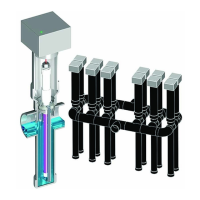
1. Install the 3-inch disinfection chamber in place at the site.
a. Position the disinfection chamber in the ground or in the tank.
b. Connect the hubs to the inlet and outlet pipes.
3-Inch Disinfection Chamber
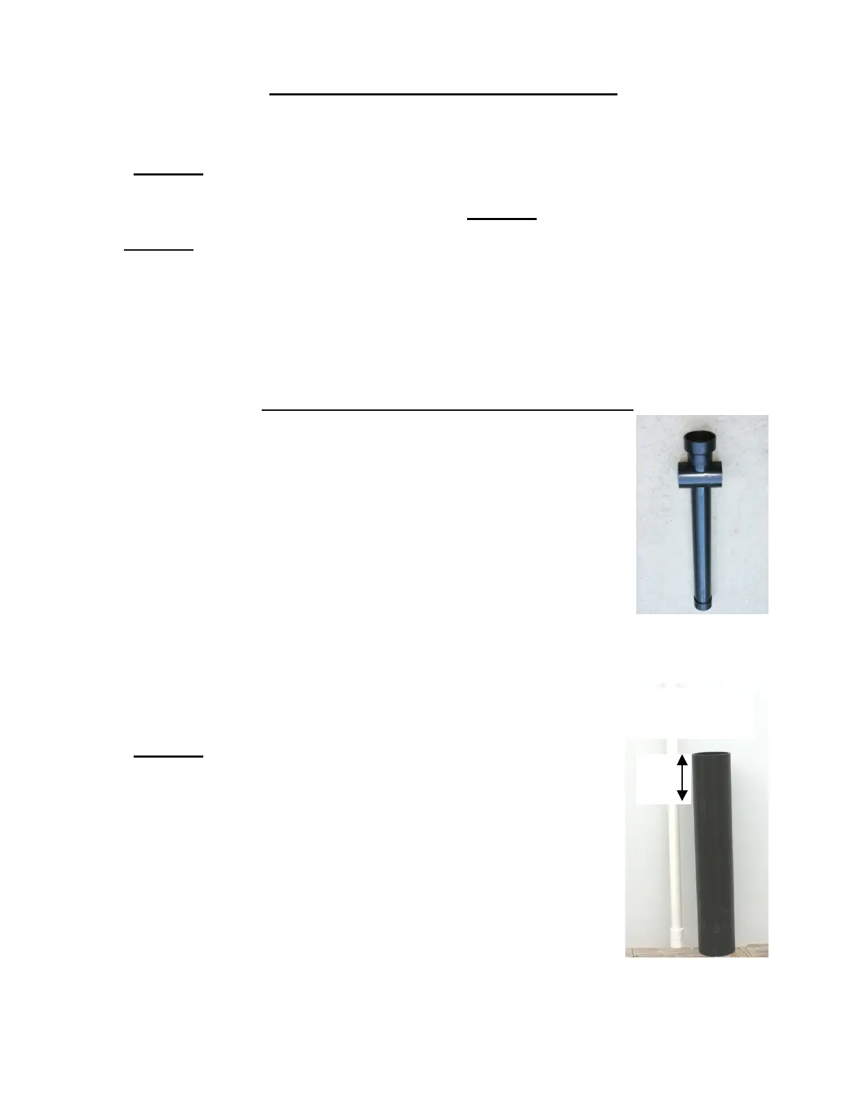
2. Cut the 4-inch riser pipe to meet the job needs. The 1-inch lamp handle may be cut to
length after cutting the riser pipe.
a. Use the 4-inch ABS inlet pipe connection to the pretreatment
unit as a reference point.
See Figure 1 (page 3).
b. The lamp handle upper end should be cut so it will be
approximately 6 inches from the top of the riser pipe.
c. Bond the 4-inch riser pipe to the chamber sub-assembly.
d. Bond the second PVC white threaded female adapter to the
top or plain end of the white PVC pipe handle.
White PVC Handle and
4-inch Riser Pipe