SALCOR INC
Page 8 of 14
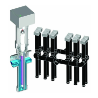
11. Install the Watertight Conduit connector to the side of the
Junction Box and secure it with the nut on the inside. Use a little
Silicone Adhesive Sealant, also called RTV, on the O-ring of the
watertight conduit connector to assist in waterproofing.
Installing Watertight Conduit Connector
12. Attention Installers!! The SALCOR Model 3G Unit requires a specific
separate independent 10-15-amp circuit breaker on the main electrical panel.
The Salcor UV Unit circuit breaker should be separate from the circuit
breakers for the pumps, etc.
No other electrical unit should be connected to the Salcor 3G Unit circuit
breaker.
13. The UV Unit operates on 120 VAC single-phase (50 or 60 Hz) power and consumes
40 watts.
14. Bring the power wires and alarm wires into the junction box via the waterproof
conduit connection. Seal the outside of the flexible conduit pipe to the waterproof
connector with Silicone Adhesive Sealant. The installer is responsible for ensuring
that the external flexible wire conduit connection(s) containing
the power and/or alarm wires to the junction box are
WATERTIGHT!!
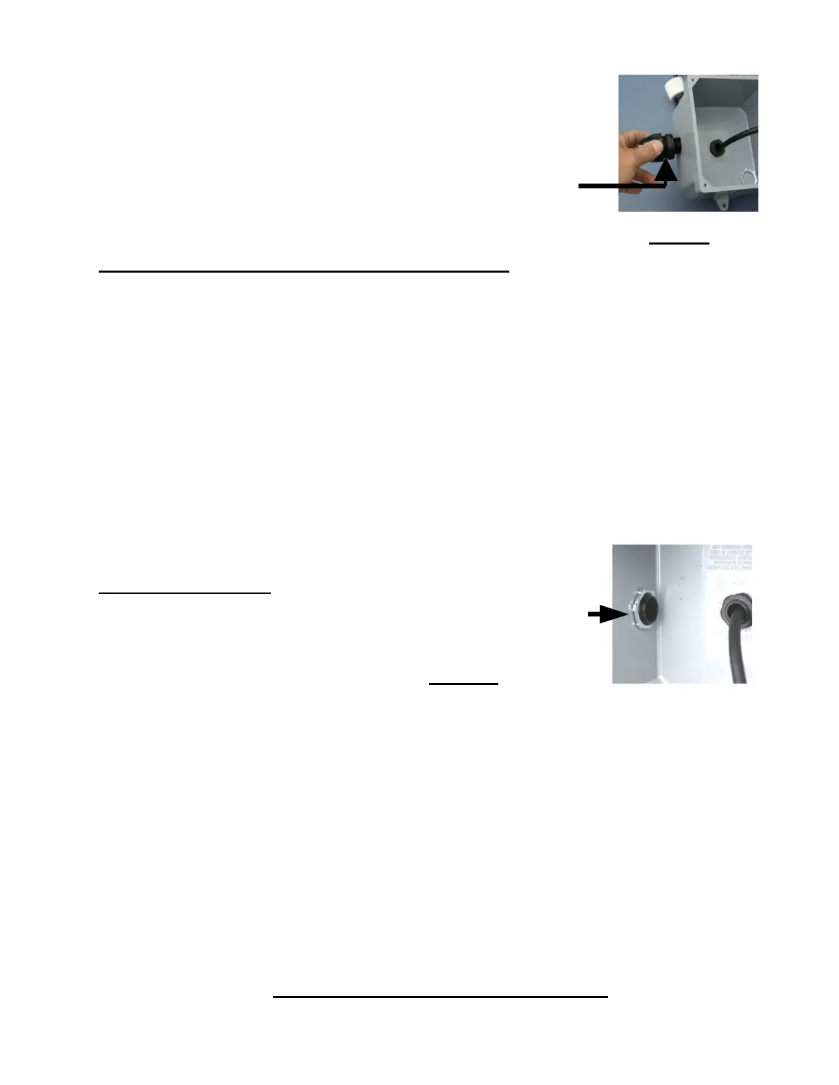
Watertight Conduit Connector Nut Inside of the Junction Box
15. Attach the power and alarm wires to the appropriate terminal
block connections on the alarm board. See Figure 4 (Page 10).
The alarm contacts are compatible with external alarm circuit units furnished by
others that use either normally open (N/O) or normally closed (N/C) contacts. Note:
N/O means the contacts are OPEN when there is NO POWER to the alarm board
relay. The contacts are rated for up to 240 volts and up to 2 Amps. Select the common
connection terminal screw and then use either the N/C or N/O connection terminal
screw that complies with the external receiving alarm circuit requirement.
16. Attach the lid to the junction box with 4 screws.
17. Allow the effluent to start flowing through the 3G Unit.
18. Turn on the circuit breaker at the main electrical control panel. The Green Indicator
Light on the junction box lid should now be shining, indicating that the 3G Unit is
operating properly. The installation is now complete.
IV. MAINTENANCE AND SERVICE