Do you have a question about the SALCOR 3G and is the answer not in the manual?
Lists components included in the shipping carton for the UV unit.
Lists additional materials the installer must provide for installation.
Highlights risks of electric shock from improper grounding and harmful UV light exposure.
Describes connecting the unit in a ground installation scenario to drain pipes.
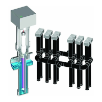
Details connecting the unit within a pump tank system.
Steps for positioning the 3-inch disinfection chamber and connecting pipes.
Instructions for cutting the 4-inch riser pipe and 1-inch lamp handle to size.
Guides on connecting the lamp cable socket to the UV lamp pins, emphasizing secure contact.
Procedures for carefully inserting the UV lamp into the quartz tube without damage.
Steps for sealing threaded connections with Teflon tape and tightening the gland nut.
How to clean the Teflon sheath and lubricate rubber gaskets for proper function.
Guides for inserting the frame/handle assembly and ensuring correct rotational alignment.
Instructions for tucking excess cable and securing the junction box to the riser pipe.
Steps for installing the conduit connector to the junction box and ensuring a watertight seal.
Requirements for a dedicated circuit breaker and connecting power/alarm wires.
Procedures for final checks, including effluent flow and indicator light status.
Detailed steps for replacing the UV lamp, including safety and disassembly.
Steps to turn off power, remove the junction box, and lift out the sub-assembly.
Instructions for cleaning the chamber and disconnecting the old UV lamp.
Guides on connecting the new lamp, seating it correctly, and reassembling the handle.
Procedure for cleaning the Teflon sheath using detergent and isopropyl alcohol.
Instructions for reinserting the cleaned assembly and verifying operation via indicator light.
Connect alarm wires to the appropriate terminal block (TB5) for your specific alarm circuit requirements.
Connect power wires to the Power Inlet Terminal Block (TB4) and the ground wire to the ballast.
Explains how 120 VAC power is fed, routed through fuses and terminal blocks to the ballast and UV lamp.
The Green Indicator light shows when there is correct lamp current.
Identifies connection points S & T on the alarm relay contact terminal block TB5.
Covers defects in material/workmanship for 24 months; repair/replacement at factory.
Excludes misuse, negligence, external parts, and consequential damages.
| Brand | SALCOR |
|---|---|
| Model | 3G |
| Category | Accessories |
| Language | English |