EN | 29SMARTY XP v2020.3
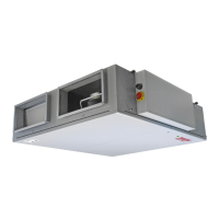
N(L1)
PE
4 3 2 1
230VAC
ON/OFF
N
L1
L1
M3
PE PE
DO4 (L(L2))
DO3 (L(L2))
230VAC
ON/OFF
N
L1
L1
M2
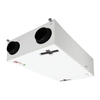
8.1.7. CONNECTION OF REMOTE CONTROL PANEL OR MODBUS
Wiring diagram.
Automation controller F zone, X18 connector.
6ZLWFKSRVLWLRQIRU;FRQQHFWRUFRQ¿JXUDWLRQ
Switch Position Purpose
S2 1 5OLQHWHUPLQDWLRQUHVLVWRU2Q2ႇ
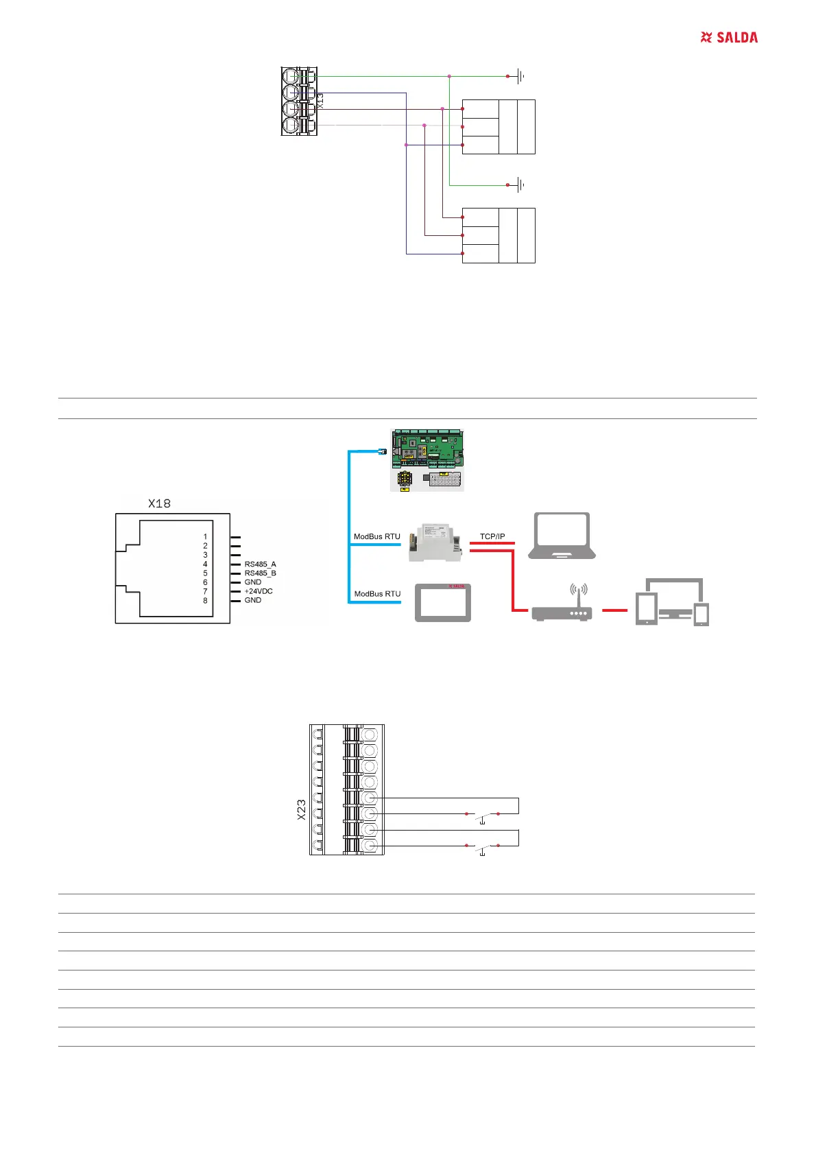
8.1.8. ),5(3/$&(&211(&7,2160$57<;3
Wiring diagram.
Automation controller C zone, X23 connector.
1234 5678
-Fire Place II
DI4
+12VDC
+12VDC
DI3
-F
ire Place I
LED INDICATION
miniMCB miniEX1
LED1 9PLQL0&%SRZHULQGLFDWLRQ:PRGH LED1 EX1 status LED
LED2 9PLQL0&%SRZHULQGLFDWLRQ
LED3 9PLQL0&%SRZHULQGLFDWLRQ21PRGH
LED4 MiniMCB status LED
LED5 Communication line Transmit indication
LED6 Communication line Receive indication
LED7 24V peripheral POWER ON indication
 Loading...