EN | 9SMARTY XP v2020.3
• Before commencing the installation of the unit, please check if all ordered equipment have been delivered. Any variation from the ordered equip-
ment list must be reported to the product supplier.
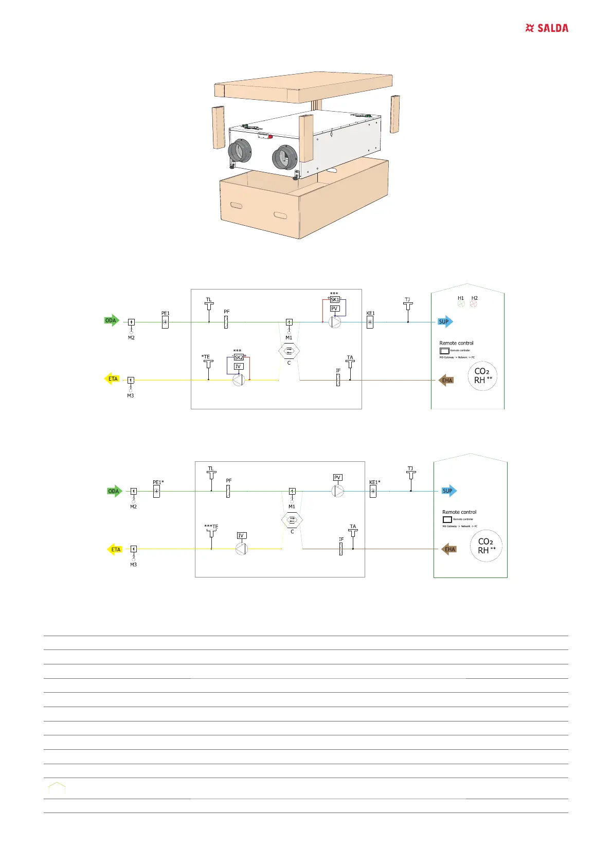
5.4. PIPING AND INSTRUMENTATION DIAGRAM
Figure 5.4.1. Smarty XP 1.1 (*Exhaust air sensor is not included with a device and should be ordered as an accessory; ** Check the manual for
details; ***Not available in Smarty 2 XP V1.1 units)
Figure 5.4.2. Smarty XP 1.2 (* Only heater or preheater can be connected at a time; ** Check the manual for details; *** Exhaust air sensor is
not included with a device and should be ordered as an accessory)
THE LIST OF COMPONENTS
C Plate heat exchanger PV Supply air fan
IF ([WUDFWDLU¿OWHU PF 6XSSO\DLU¿OWHU
IV Exhaust fan TA Extract air temperature sensor
TE Exhaust air temperature sensor TJ Supply air temperature sensor
DTJ Extract air temperature and humidity sensor CO
2
CO
2
sensor
RH RH sensor PC Computer
KE1 Electric heater PE1 Electric pre-heater
M1 By-pass damper M2 Outdoor air damper actuator
M3 Exhaust air damper actuator SK1 Supply air pressure sensor
SK2 Exhaust air pressure sensor TL Outdoor air temperature sensor
Ventilated premises MB-Gateway 1HWZRUNPRGXOH
NET 1HWZRUN RC Stouch or ST-SA-Control remote control panel
 Loading...