EN | 35SMARTY v2023.2
Since the pre-heater must be connected according to the factory settings, the settings should be changed in the environment of the MB-Gateway
WEB application service or on the ST-SA-Control panel.
SETTINGS IN THE ENVIRONMENT OF THE MB-GATEWAY WEB APPLICATION SERVICE
Change the settings as follows:
• Service password 4444;
• Service > Heaters > Heater and pre-heater position;
• Select either the heater or pre-heater to be switched on the MiniMCB basic.
1
For the Stouch control panel, changing of the settings is not possible
• Service > Digital inputs > Heater protection inputs
Set the manual and automatic protection device modes of the heater or pre-heater (NC by default).
• Service > Heaters > Supply air heater or outdoor air pre-heater
Set either a heater or pre-heater and the type of the heater or pre-heater as well as the steps to be performed in case of protection signal activation.
SETTINGS WITH THE ST-SA-CONTROL PANEL
1. Go to Menu / Service / Heaters. Enter the Service password (the initial password – 4444);
2. Select Control Position as 'Heater on basic' or 'Pre-heater on basic'.
3. Go to Menu / Service / Heaters / Heaters and set the heater type
• 0..10VDC – 0-10 control,
• ON/OFF – On/O control,
• None – heater switch-o, and also specify the system response protection signal.
4. Go to Menu / Service / Heaters / Preheater. Set type ’0..10VDC’ 0-10 control, ’ON/OFF’ On/O control, ’None’ – pre-heater switch-o. Set the
system response protection signal.
5. Go to Menu / Service / Digital inputs / Heater protection. Set the manual and automatic protection device modes (NC by default).
6. Go to Menu / Service / Digital inputs / Preheater protection. Set the manual and automatic protection device modes (NC by default).
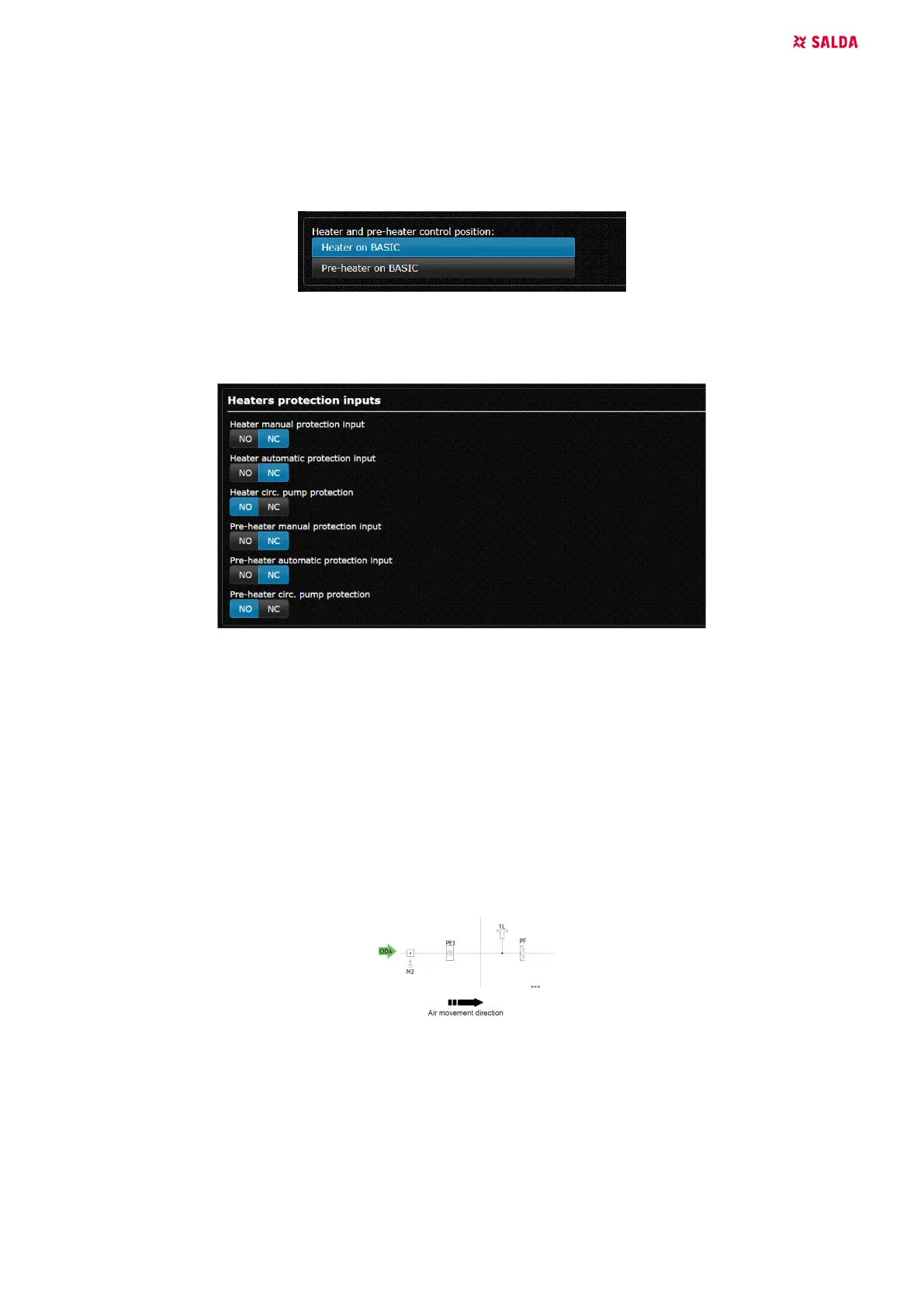
Pre-heater installation diagram
Installation based on air direction Air Damper M2 > Pre-Heater PE1 > Air Handling Unit.
Only pre-heaters with up to 2 kW power circuit can be connected directly to the control board. The pre-heaters of higher power must be connected
to separate electric power circuit.
Heater Installation Diagram
Electric heater must be installed inside the air duct. The layout is based on airow direction ELECTRIC HEATER > SUPPLY AIR SENSOR (TJ).
 Loading...