40 | EN SMARTY v2023.2
Air Handling unit can be controlled with remote control panel POS8. Remote controller connects with S300 controller via KNX PL-Link interface.
T15:1;2 – terminals of AHU’s controller for KNX devices.
Same interface and controller terminals are used for QMX3 room sensors P30, P40 and P70 connection.
Air Handling unit can be connected to the Building Management System via BACnet IP or Modbus (RS485).
BACnet is connected to the T5 connector (RJ45) of S300 controller which has default BACnet settings:
BACnet Vendor Identier: 7
BACnet Vendor Name: Siemens Building Technologies
Default BACnet/IP port: 47808 (0xBAC0)
Default Device Object Instance number: 1
All S300 devices of the same BACnet system must have dierent device object instance numbers.
Modbus RTU connects to the T12:1;2;3 terminals (Modbus Slave Port1) of the S300 controller which has default RS485 port1 settings:
Baudrate: 19200 bps
Data: 8 Bit
Parity: Even
Stop bit: 1
Slave address: 1
Page
Page
Project template with identification structure in accordance with IEC standard: Page structure with higher-level function and mounting location
Ed.
1
Original
IEC_tpl001
EPLAN
mindaugasbeleckas +
Date
Date
Replaced by
Dampers
1
Modification
0 76
Appr.
Replacement of
8 93
2
4
2022-01-17
EPLAN Software & Service
GmbH & Co. KG
2
2
=
Name
5
2/
1
2
Outside air damper control signal (L, 230V)
Output digital relay 24-230 V AC, max 6.3A, normally open/closed
Q34
Ref
D1
GND
+24VDC
Smoke
detector
T3
T7
3 124
Operation indication output signal (L, 230V)
Output digital relays 24-230 V AC, max 6.3A,
normally open/closed
Q24
Connected by user
213
T19
1
2
Alarm indication output signal (L, 230V)
Output triac, 230V AC, max. 10A (<1s),
nominal current: 0,05-1A.
Y1
12
KNX+
KNX-
isolation, 40mA rated
T15
To air quality sensor
or remote controller
Ref
D2
GND
+24VDC
NO/NC switch
T3
Connected by user
213
T12
Modbus slave port1 over
RS485, HMI/RU interface
RS485 A+
RS485 B-
RS485 Ref
12
3
Modbus RTU
Figure 8.9.1. Air quality sensor, remote controller and BMS connection to the S300 controller
After connection of air quality sensor or remote controller, conguration has to be performed. For more information see section "ACCESSORIES
SETUP (VERSION S300)".
Modbus TCP/IP connection can only be implemented via additional device - MB-Gateway. Controller’s Modbus Slave Port1 or Port2 can be used
for Modbus TCP/IP connection (see section "CONNECTION TO WIRING TERMINALS (VERSION S300)" for location of the Port2).
USB connector for S300 controller is used to connect WIFI stick and make controller as WIFI access point to control the unit with smartphone or
tablet using ABT Go application. USB connector can also be used for S300 controller rmware updates.
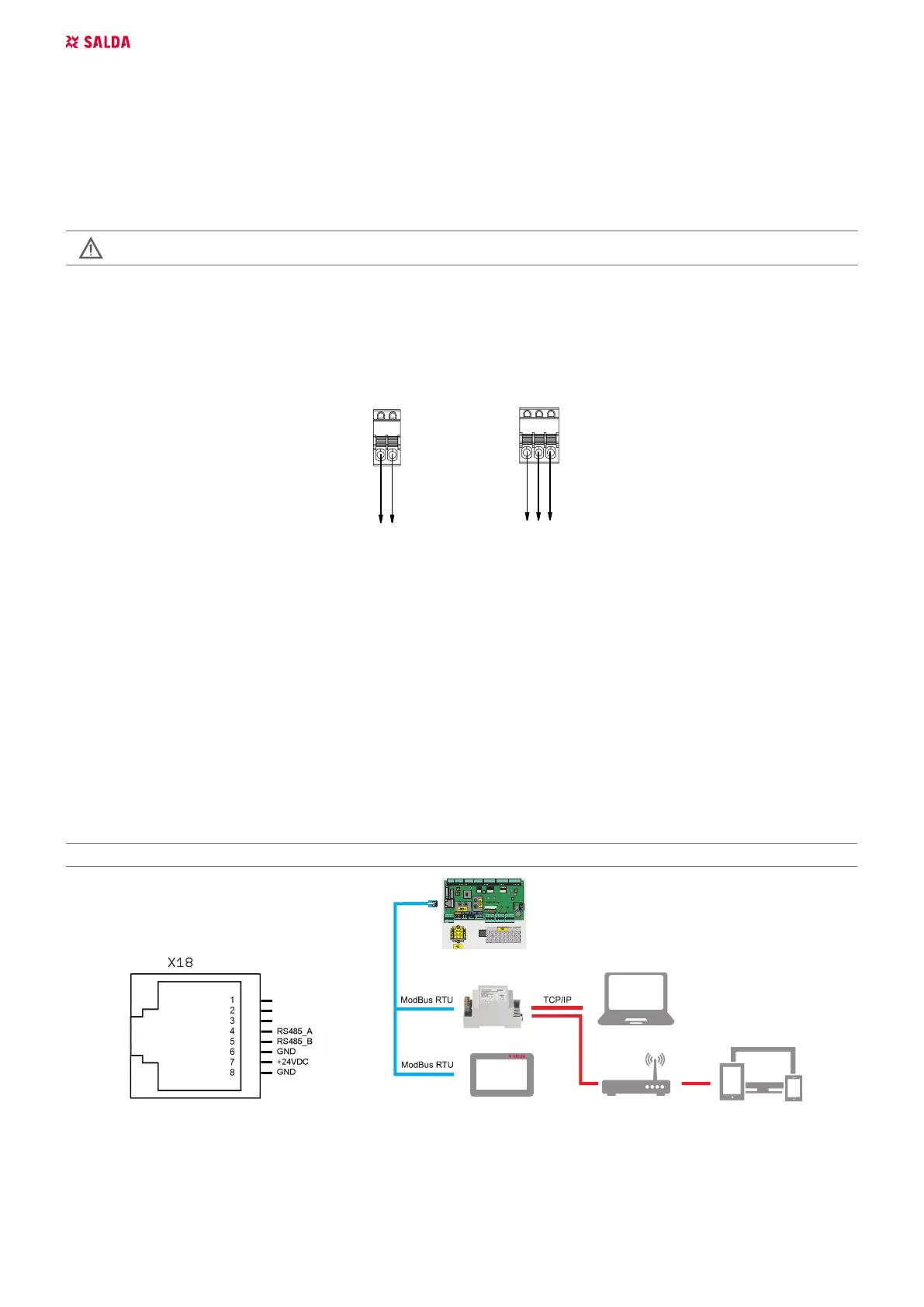
8.10. CONNECTION OF REMOTE CONTROL PANEL OR MODBUS (VERSION 1.1 / 1.2)
Wiring diagram.
Automation controller F zone, X18 connector.
Switch position for X18 connector conguration
Switch Position Purpose
S2 1 120R line termination resistor (On/O)
8.11. FIREPLACE PROTECTION/SYSTEM MODE SWITH/RAPID VENTILATION SWITCH INPUT
(VERSION S300)
T3 connector can be used for connecting one of the following function to D2 digital input:
1. Fireplace protection;
2. System mode switch;
3. Rapid ventilation switch.
 Loading...