38 | EN SMARTY v2023.2
By default, D1 digital input is congured as Smoke detector input and set to NO, if needed NC contact type, then it must be recongured. See
section "ACCESSORIES SETUP (VERSION S300)".
8.4. EXTERNAL CO
2
/RH SENSORS (VERSION 1.1 / 1.2)
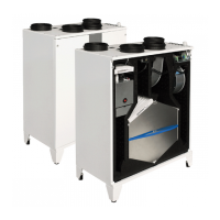
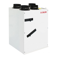
Smarty XP 1.1 / Smarty XV 1.1 units feature two connections for external CO
2
/RH (input 0-10VDC) sensors.
Sensors connection:
+24VDC
AI4 (0-10V)
GND
12345678
AO1
GND
Vin
Transmiter 1
Supplyair CO2or
RH (input 0-10VDC)
+24VDC
GND
123
AI1(0-10V)
Vin
GND
AO1
Transmitter 2
Smarty 3X V 1.1 and Smarty 4X V F2 1.1 come with the integrated RH sensor connected.
Smarty XP 1.2 / Smarty XV 1.2 units feature one connection for external CO
2
/RH (input 0-10VDC) sensors.
Sensors connection:
+24VDC
AI4 (0-10V)
GND
12345678
AO1
GND
Vin
Transmiter 1
These sensors feature 3 functions: Supply RH, Extract RH and Extract CO
2
.
Supply RH transmitter shall be installed inside supply air duct.
Extract RH and Extract CO
2
transmitters shall be installed inside extract air duct or room.
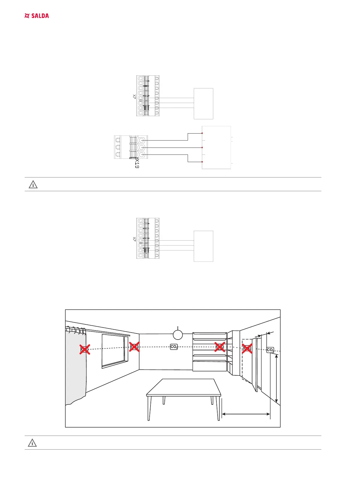
8.5. ROOM CO
2
TRANSMITTER INSTALLATION RECOMMENDATION
min. 50 cm
min. 60 cm
150 cm
max. 400m
2
If the duct CO
2
transmitter is used, it must be installed in the extract air duct. To install duct transmitters, hole drilling tools
are required .
 Loading...