1. GENERAL
1.1 Applications
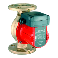
Pumps designed to pump fluids (natural and industrial waters,
hydrocarbons and solvents) in the fields of accommodation, agri-
culture, industry ...
1
.2 Specifications
• Service pressure : 10 and 16 bar
• Temperature range
Mechanical seal : - 20 ° to + 120 °C (optional 140 °C)
Fabric packing : 105 °C maxi
•
Ports DN Suction DNS : 50 to 500
Discharge DND : 32 to 500
2. SAFETY
Read this data sheet carefully before installing and starting up.
Pay special attention to the points concerning the safety of the
equipment for the intermediate or end user.
2.1 Symbols used in the manual
Calls attention to a potential risk that might affect safety.
Instruction concerning electricity.
Warning.
Before any putting-into-service of the motor-pump, make sure
the coupling pr
otective cover is present.
3. TRANSPORT AND STORAGE
When taking delivery of the equipment, check that it has not
been damaged in transit. If anything is found wrong, take the
necessary steps with the carrier within the allowed time.
If the equipment delivered is to be installed at a later
time, store it in a dry place and protect it from
impacts and outside influences (moisture, frost, etc.).
The set will be handled taking it at the baseplate and pr
ef
erably
using blankets. Never use the motor eye bolts (see FIG. 1).
In case of frost risk, and for prolonged shutdowns, drain the pump
and auxiliary circuits, close the isolating valves.
Storage shor
ter than 3 months:
all zones
,
bef
or
e star
ting up,
tur
n the motor-pump by hand.
Storage shorter than 6 months:
temperate zones, before starting up, turn the motor-pump by hand;
other zones:
Dism
antle the pump to r
eplace all g
ask
ets and all f
ittings.
Check the bearings (non oxidation - lubrication).
Check the coupling catches.
Check for perfect lubrication.
In any case, check the alignment of shafts.
After prolonged shutdown, never start the pump without having
perf
or
med the chec
ks of f
irst putting into service.
For pumps with IP55 motor
s : the plugs blanking the condensates
discharge ports must be removed for the whole time the equip-
ment is in storage (these plugs are supplied with the pump).
4. PRODUCTS AND ACCESSORIES
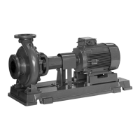
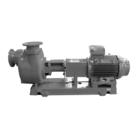
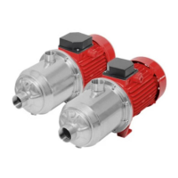
4.1 The pump
• Centrifugal, single-stage, horizontal shaft.
• Axial suction, radial or upward tangential discharge according
to the type of pump.
• Mounting brackets under the pump body.
• Main dimensions complying with standard NFE 44111.
4.2 The motor
Standardized, linked to pump shaft by semi-elastic coupling,stan-
dard without spacer.
M
onobloc shaft-guiding rolling bearing, lubricated by grease.
Tightness at center hump by mechanical seal.
Cast iron baseplate according to standard NFE 44111.
• Frequency : 50 Hz and 60 Hz
• Speed (in 50 Hz) : 1450 rpm and 2900 rpm
(in 60 Hz) : 1750 rpm and 3500 rpm
• Three-phase winding
≤ 4 kW : 230/400 V
o
ver : 400 V
∆
• Insulation class : F
• Protection index : IP54 and IP55
(according to motor)
* IP55 motors : the plugs blanking the condensates discharge ports have
been removed (these plugs are supplied with the pump).
4.3 Accessories (optional)
• Counter-flanges, gaskets and bolts • Motor protection circuit-
breaker • Pressure gauge kit • Check valve •Anti-vibration slee-
ve • Spacer coupling •
5. INSTALLATION (SEE FIG.2)
5.1 Mounting
Install the motor-pump in a place easy to reach, protected from
frost, and as close as possible to the water drawing point in order
to limit the suction head loss.
- Mounting on concrete foundation (
D), with fastening through
anchor bolts (A - FIG.3); the foundation should be widely sized,
its weight should be about 2 to 3 times the motor-pump weight.
- Under the concrete foundation, provide for insulating material (cork
or reinforced rubber) to prevent the propagation of vibrations.
Motor-pump anchoring (see FIG.3)
- During anchoring operations, do not flange the pump to pipes.
Continually check the motor-pump levels and alignment (see
next par
agr
a
ph: ”Check of the shaft-line alignment”).
- Clean the foundation (
D), position anchoring rods (A) in the
holes, place the motor-pump and install nuts (A).
- I
nsert steel wedges (B) of thickness ≥ 10 mm between baseplate (E) and
the foundation, distributed on either side of anchor bolts (A - FIG.3).
- The wedging should provide the motor-pump with perfect hori-
zontal position and place it at the required height.
- Under
pour concr
ete in f
oundation holes (
C).
After concr
ete set
-
ting, progressively tighten baseplate (
E) on the wedges while
checking the alignment and levels.
- P
our lo
w shrinkage concrete inside the base
(E) thr
ough hole
(F).
Do not use rapid hardening cement.
Anchor bolts to be used:
Type of standardized
Part Length Dia. Threaded-part
basepla
te
number
(mm)
(mm)
length (mm)
2
740705 200 16 40
3 740706 200 16 40
4
740707
300
20
60
5
740708
300
20
60
6 740709 300 20 60
7 740710 350 24 100
8 740711 350 24 100
9 740712 350 24 100
Chec
k of the shaft-line alignment accor
ding to standar
d NFE
44190 (see FIG.6).
The motor pump alignment, carefully performed in
factory, must always be checked and corrected
after final attachment of the baseplate and after disassembly-
assembly operations (see FIG.6).
7
ATTENTION !
A
TTENTION
!
A
TTENTION
!
ENGLISH