10-7
A. OIL LEVEL MAINTENANCE CIRCUIT
FUNCTION
The oil level maintenance circuit ensures that the correct oil level is maintained in the rear gearbox.
OPERATION
The gear pump (1) draws in oil from the front gearbox and sends it to the rear gearbox.
This circuit includes a mesh filter (2) to remove larger particles.
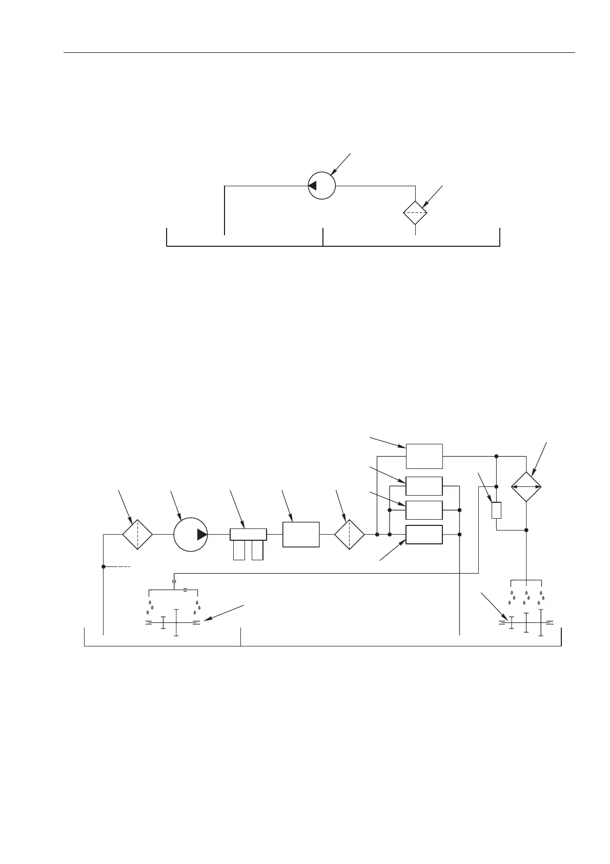
B. STEERING AND POWER SHIFT CONTROL CIRCUIT
FUNCTION
The steering and Power Shift control circuit sends oil under pressure to the controls for the Power Shift transmission and
the steering. This circuit also sends oil under pressure for lubrication of the primary shaft and the rear PTO.
OPERATION
The gear pump (1) draws in oil (through filter (2)) from the rear gearbox and sends it under pressure to the power steering (3)
via the resonators (4). The oil is then sent under pressure through the pressurised filter (5) to the Power Shift control valves (6),
the services control valve (7), the main clutch control valve (8) and the range gearbox control valve (9). Excess oil is then sent
to the rotating parts of the rear PTO (10) and the primary shaft (12).The circuit also includes an oil-cooler bypass valve (13)
(set to 15 bar (217.5 psi)) that prevents an excessive increase in the lubrication circuit pressure on cold starting of the tractor
and during operation in very cold climatic conditions.
1
2
D000
1230
REAR GEARBOX FRONT GEARBOX
1
2
3
4
5
6
7
8
10
11
12
13
9
D000
1280
REAR GEARBOX FRONT GEARBOX
HYDRAULIC SYSTEM