10-14
2. HYDRAULIC PUMP
FUNCTION
·
The rotation and torque of the pump shaft are con-
verted into hydraulic energy and the flow of pressu-
rised oil is regulated in accordance with the demand
from the various actuators.
·
It is possible to vary the pump delivery by changing
the angle of the swash plate.
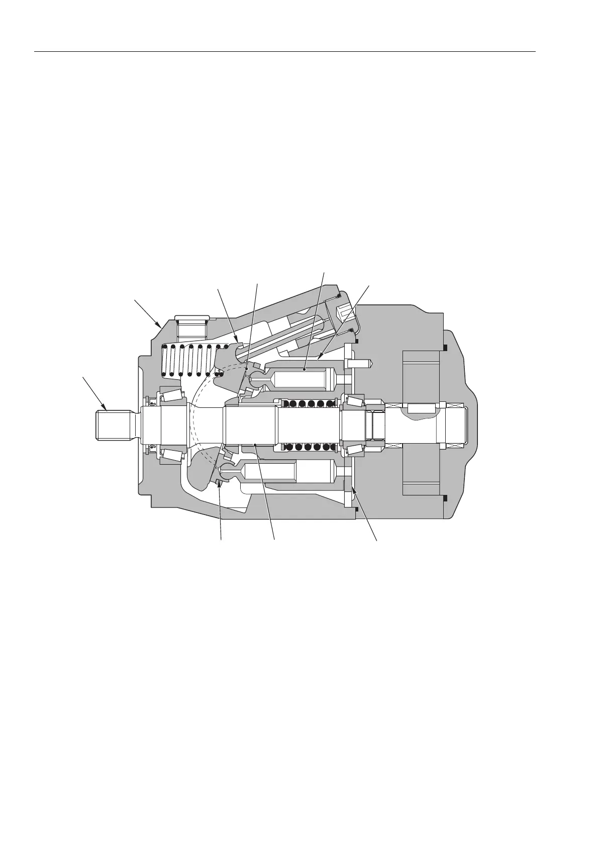
CONSTRUCTION
·
The cylinder block (4) is keyed onto the shaft (1) by
the broaching
B
. The shaft (1) is supported by the
front and rear bearings.
·
The ends of the pistons are spherical; the piston shoes (6)
are staked over to form a single assembly. The piston (5)
and shoe (6) together form a ball joint.
·
The swash plate (3) has a flat surface
A
against which
the piston shoes (6) slide as the cylinder block ro-
tates.
D0003190
4
3
2
1
5
76
A
B
·
The pistons (5) stroke axially inside the cylinder
bores in the cylinder block (4).
·
The rotation of the cylinder block (4) pressurises the
oil in the cylinder bores; the valve plate (7) deter-
mines the inlet and outlet ports .
The oil in each of the cylinder bores is drawn in and
discharged through the openings in the valve plate (7).
HYDRAULIC PUMP