10-20
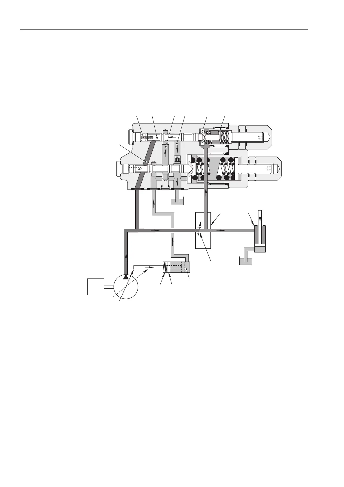
b. When a control valve lever is operated
·
When a control valve lever is shifted from the NEUTRAL position, this generates an
LS
signal corresponding to the
pressure
PLS
.
·
The
LS
signal pressure in chamber
a
moves the spool to the left, thereby connecting passages
d
and
e
.
Chamber
X
is thus depressurised and the swash plate is moved to the maximum delivery position by the action of the
spring (5).
·
System balance is restored when the pressure difference
D
PLS
acting on the spool (1) balances the force exerted by
the spring (2) and thus re-opens the connection between passages
c
and
d
.
M
Min Max
D000
0470
8
7
65
21
PLS
PP
T
PEN
a
b
X
ed
c
f
PP
LOAD SENSING VALVE, PRESSURE CONTROL VALVE