
N
naguirreAug 13, 2025
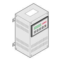
What to do if I have a problem with the low voltage cable on my SAMES KREMLIN GNM 100-A Controller?
- Ddennis06Aug 13, 2025
If you're experiencing issues related to the low voltage cable with the SAMES KREMLIN Controller, the suggested solution is to replace or repair the low voltage cable.