86 | SAMLEX AMERICA INC.
SECTION 4 | Parameter Setup
4.8.2.3 WAKE UP POINT (Table 4.9, Parameter Setup Screen No.3)
INFO
For more information on use and application of Power Save Functions, please refer to Sections 4.6.3 & 4.6.4 in
the "Evolution Series Inverter/ Charger Owner's Manual for Models EVO-1212F/1212F-HW/1224F/1224F-HW."
If the unit is in "Power Save Mode" and the value of the AC power of the load rises to "WAKE UP POINT", the unit will
quit "Power Save Mode" and will start operating in full voltage "Inverting Mode".
4.8.2.3.1 Programming Steps for Parameter "WAKE UP POINT"
ð ð
E V O - 1 2 1 2 F I n v e r t i n g
A C o u t p u t : 1 2 0 . 0 V
< 0 . 1 0 A
6 0 . 0 0 H z
Enter Key Down Key x 2 times
Any Operating Mode Screen from
Fig 3.1 to 3.5
[Above screen is Screen 1 of Fig 3.2(a)]
Password 8052
See Section 4.3.1
See Table 4.9, Parameter Setup
Screen No. 3
for programmable options
S e l e c t G r o u p
* C H A R G E C U R V E
ð
S e l e c t P a r a m e t e r
* O T H E R F U N C T I O N
ð
S e l e c t P a r a m e t e r
O T H E R F U N C T I O N
* P O W E R S A V I N G
0 = D i s a b l e
S e l e c t P a r a m e t e r
O T H E R F U N C T I O N
* W A K E U P P O I N T
7 W
Down Key x 4 times
Enter Key
P a s s w o r d k e y i n
0 0 0 0
ð
Enter Key
S e l e c t P a r a m e t e r
O T H E R F U N C T I O N
* W A K E U P P O I N T
7 W
ð
Enter Key
4.8.2.4 REMOTE SWITCH (Table 4.9, Parameter Setup Screen No. 4)
This selection is used when ON/OFF control of EVO™ Inverter/Charger is desired through external 12 VDC signal fed
to Remote ON/OFF terminals on the Front Panel of EVO™ Inverter/Charger [(i)15, Fig 2.1 in EVO™ Inverter/Charger
Owner's Manual for EVO-2212/3012/2224/4024 and (ii) 16, Fig 2.1 for EVO-1212F/1212F-HW and EVO-1224F/1224-
HW].
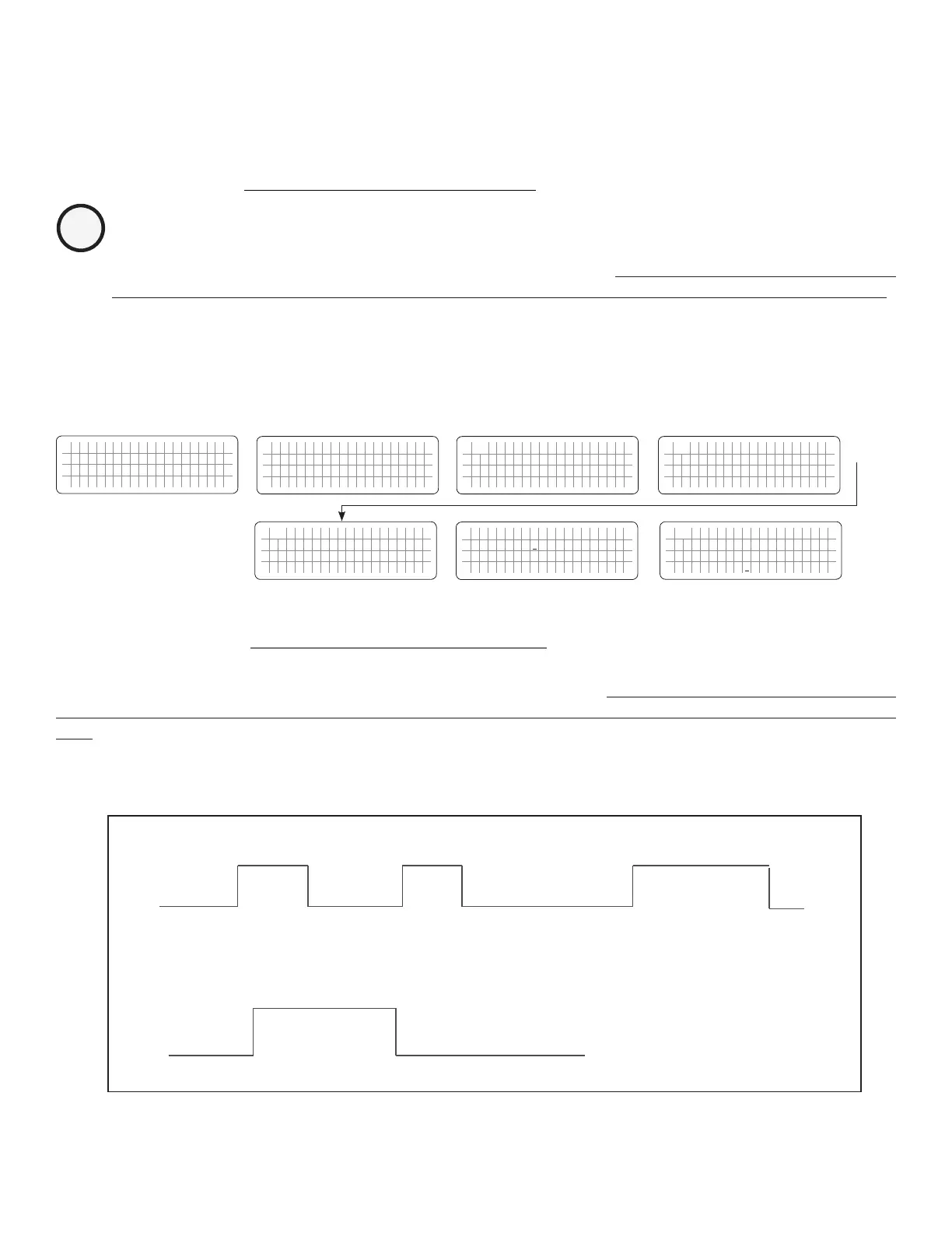
On/Off Logic Diagram is shown in Fig 4.8 below:
Fig 4.8. On/Off Logic Diagram for Remote Switch Options
Option “0 = Button”
(Default)
External 12VDC signal is fed through Push Button Type of Switch.
•
Momentary contact of Push Button > 2 sec will switch EVO Inverter Charger ON
External +12V signal is fed through external On/Off Switch or through
relay contact closure. EVO will be ON as long as the external On/Off
switch is ON / relay contact is closed.
Option “1 = Switch”
1
st
12VDC input
> 2 sec will switch ON
EVO Inverter Charger
After power ON,
12VDC input < 5 sec
will have no effect
After power ON,
12VDC input > 5 sec
will switch OFF
EVO Inverter Charger
12VDC input is
available - Power On
No 12VDC input
for 2 sec - Off
 Loading...