3
R. 03/18 835 807
SAMOA Industrial, S.A. · Pol. Ind. Porceyo, I-14 · Camino del Fontán, 831 · 33392 - Gijón - Spain · Tel.: +34 985 381 488 · www.samoaindustrial.com
2018_03_15-11:00
EN
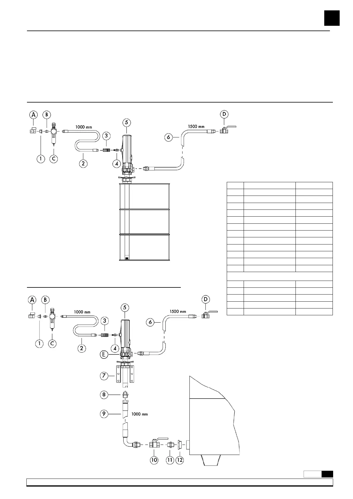
See figures 3a and 3b for a typical installation with all the recommended
accessories for the pump to operate correctly.
Pos. Description Part No.
1 Nipple 945516
2 Air hose 246010
3 Quick coupling 253114
4 Connection nipple 259014
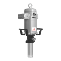
5 Pump 353110
6 Outlet hose 362101
7 Wall bracket 360102
8 Nipple 945552
9 Suction hose 362400
10 Valve 950306
11 Nipple 945555
12 Nipple 945565
Optional
A Valve 950319
B Nipple 239000
C Filter regulator 240500
D Valve 950300
E Safety valve 609007
DRUM MOUNTED PUMP
Fig. 3a
WALL MOUNTED PUMP
Fig. 3b
TYPICAL INSTALLATION
NOTE: The compressed air supply must be between 3 and 10 bar (40
– 140 psi), working air 6 bar (90 psi) is the recommended air working
pressure. An air shut-off valve must be installed, in order to close the
compressed air line at the end of the day. (If the air inlet not is closed
and there is a leakage at some point of the oil outlet circuit, the pump
will start automatically, emptying the container).