6 | SAMLEX AMERICA INC. SAMLEX AMERICA INC. | 7
SECTION 3 | Layout
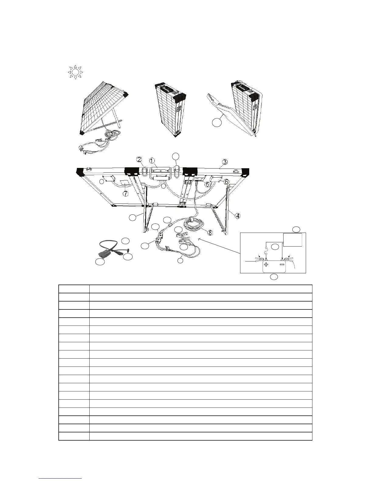
1 Carrying handle
2 Latches
3 Aluminum frame
4 Aluminum support legs with tilting arrangement
5 Solar Charge Controller MSK-10A - see Fig 3.2 for details
6 Junction Box
7 Label
8 14 ft battery cable with 2-Pole, 50A Mating Type Battery Connector at battery end and 10A fuse (11)
8A, 9A, 10A 2-Pole, 50A Mating Type Battery Connector
9 2 ft Adapter Cable with 2-Pole, 50A Mating Type Battery Connector/Battery Clamps
9B Red, Positive Battery Clamp
9C Black, Negative Battery Clamp
10 2 ft Adapter Cable with 2-Pole, 50A Mating Type Battery Connector/SAE Connector
10B SAE Connector
11 10A Fuse and Fuse Holder
12 12V Battery (not included)
13 Fuse for load(s) connected directly to the battery (not included)
14 12V load connected directly to the battery
15 Carrying Case
Fig 3.1 Overall Layout and Connection Arrangement
6
6
4
DC Load
> 10A
Fuse
Battery
+ Battery