Do you have a question about the Samson Airline 77 and is the answer not in the manual?
Describes the antenna mountings, rotation, and positioning for optimal placement.
Sets the audio signal level output through balanced and unbalanced jacks.
Displays incoming audio signal strength with a segment ladder.
Determines receiver range before audio dropout; normally left at factory setting.
Indicate which antenna is receiving the strongest, clearest signal for True Diversity switching.
Displays incoming radio signal strength with a segment ladder.
Turns the receiver power on and off; internal Power LED indicates status.
Connects the 12V power adapter; use strain relief. Do not substitute adapters.
1/4" jack for consumer audio equipment; tip hot, sleeve ground.
Sets attenuation for balanced output to -20 dBm (line) or -40 dBm (mic).
XLR jack for professional audio equipment; pin wiring detailed.
Flashes on power on, lights red for <2 hours battery life.
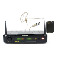
Permanently attached flexible antenna; extend fully for normal operation.
For AAA alkaline battery; observe polarity. Warning against backwards insertion.
Mutes/unmutes audio signal without affecting carrier signal; does not turn off power.
Turns transmitter power on/off. Conserve battery. Mute audio before power change.
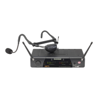
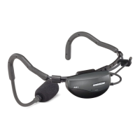
Details correct wear and microphone placement for Q Series Headsets.
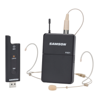
Microphone hard-wired to AH1 transmitter; positioning instructions in HM40 manual.
Reference to pages 13-14 for more information on the transmitter.
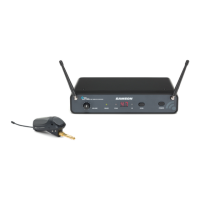
Used to attach the assembly to the horn bell; instructions in HM40 manual.
Ensure receiver and transmitter are set to the same channel for correct operation.
Position receiver for "line of sight" with transmitter; rack-mounting option.
Extend receiver antennas and place them vertically.
Gently pry off the battery cover to access the compartment.
Insert AAA alkaline battery, observe polarity, and replace cover.
Connect receiver output to amp/mixer mic level input; use XLR for cleaner signal.
Set receiver volume to minimum, connect AC adapter, and turn on receiver.
Turn on AH1 transmitter; check Power/Battery LED and receiver A/B LEDs.
Turn on amp/mixer, set receiver Volume/Level to unity gain, ensure transmitter is unmuted.
Slowly raise amp/mixer volume to achieve desired audio level.
If distortion occurs, check receiver "Peak" LED and microphone position.
If signal is weak/noisy, check gain structure and microphone proximity.
Adjust Squelch to eliminate noise when transmitter is off; minimize range if necessary.
Walk through coverage area, check RF meter for sufficient signal strength.
Details operating voltage, current, battery life, RF output, frequency stability, modulation, THD, etc.
Details receiving frequencies, oscillation, de-emphasis, IF frequency, antennas, display, controls, operating temp, voltage, current, sensitivity, selectivity, THD, S/N ratio, etc.
Lists authorized frequency ranges and specific channel frequencies for various country codes.
| Audio Frequency Response | 50Hz-15kHz |
|---|---|
| Receiver | Diversity |
| System Type | UHF Wireless |
| Polar Pattern | Cardioid |
| Receiver Type | Diversity |
| Output Connectors | 1/4", XLR |
| Operating Range | 100 m (328 ft) |