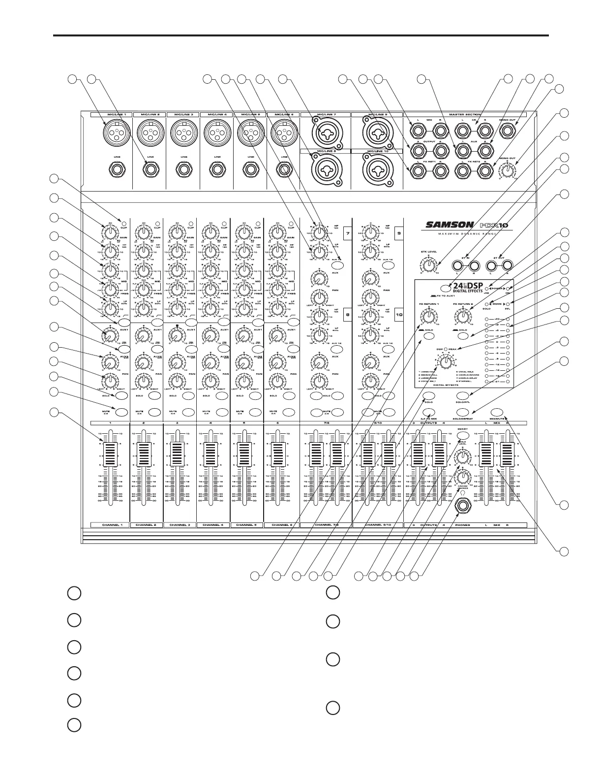
Front Panel Layout
1 CLIP – Red LED will illuminate, indicating when the GAIN
control has been adjusted too high.
2 GAIN – Used to set the input level of the mic pre and line
input.
3 HIGH FREQUENCY - Controls the high band level of the
Channel Equalizer, +/- 15 dB.
4 MID CUT & BOOST - Controls the level of mid-range ,+/- 15
dB at the frequency set by the Mid Frequency control.
5 MID FREQUENCY - Used to set the center point of the mid
band of the Channel Equalizer from100 Hz to 5KHz.
6 LOW FREQUENCY - Controls the low band of the Channel
Equalizer, +/- 15 dB at 80Hz.
7 LOW CUT – Bass roll off switch at 80Hz used to eliminate
unwanted low end rumble and hum.
8 AUX 1 – Pre fader auxiliary send that can be used with an
external effects processor, or to create a cue or monitor
mix.
9 AUX 1 PRE/POST Switch This LED back-lit switch is used
to select the point in the audio path that the channel’s sig-
nal is sent to the AUX 1 bus, either before or after the
input fader.
10 AUX 2/DSP – Post fader auxiliary send connected to the
internal 24 BIT DSP effect processor and can also be
used with an external effects processor.